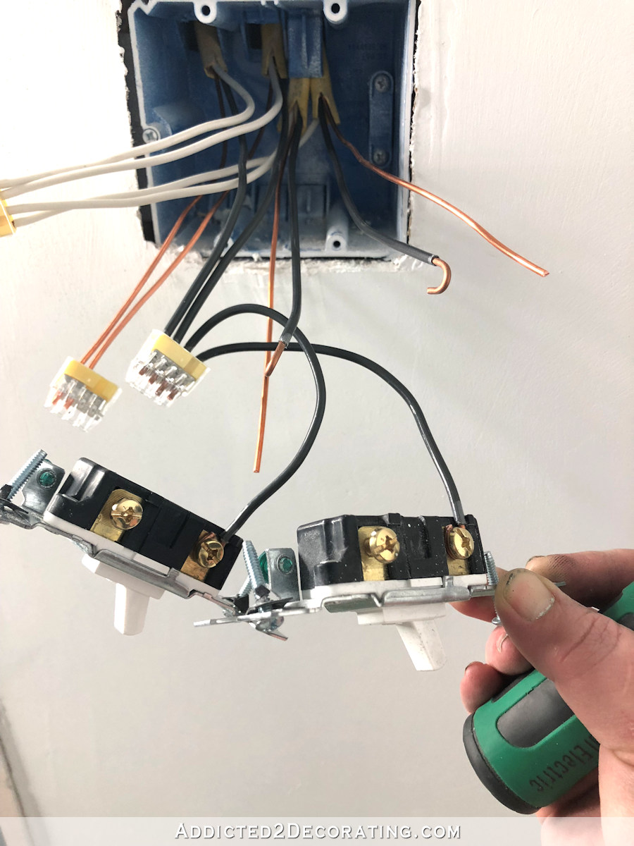
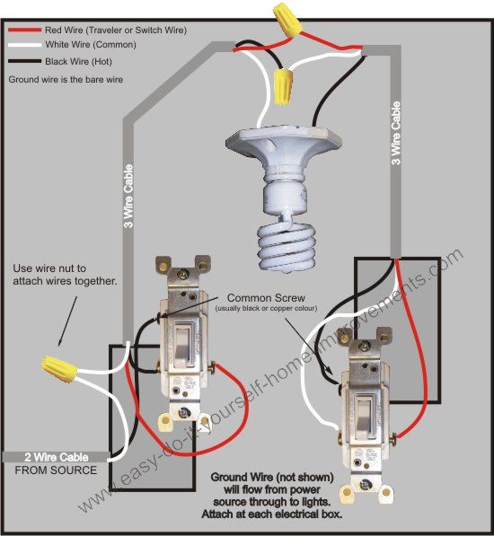
These are called terminal screws. You should see two black wires each connecting to a different screw on the right side of the switch.
How To Identify The Common Wire In A Three Way Switch Control
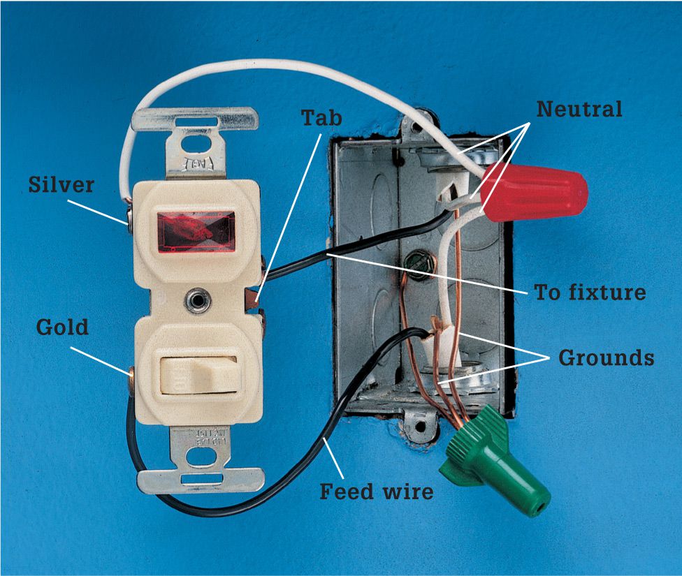
Black screw on switch. A 3 way switch has three terminal screws plus a ground screw. The white wire from the new cable connects to the fixtures hot wire terminal or hot wire lead and to the other screw terminal on the switch. It serves as the second hot wire in the switch loop. 4585 ovalhead for strat installation on a countersunk pickguard. The black hot wire goes to the brass screw or into the hole in the back of the device on the same side as the brass screw. On the other end the two white wires are wire nutted together.
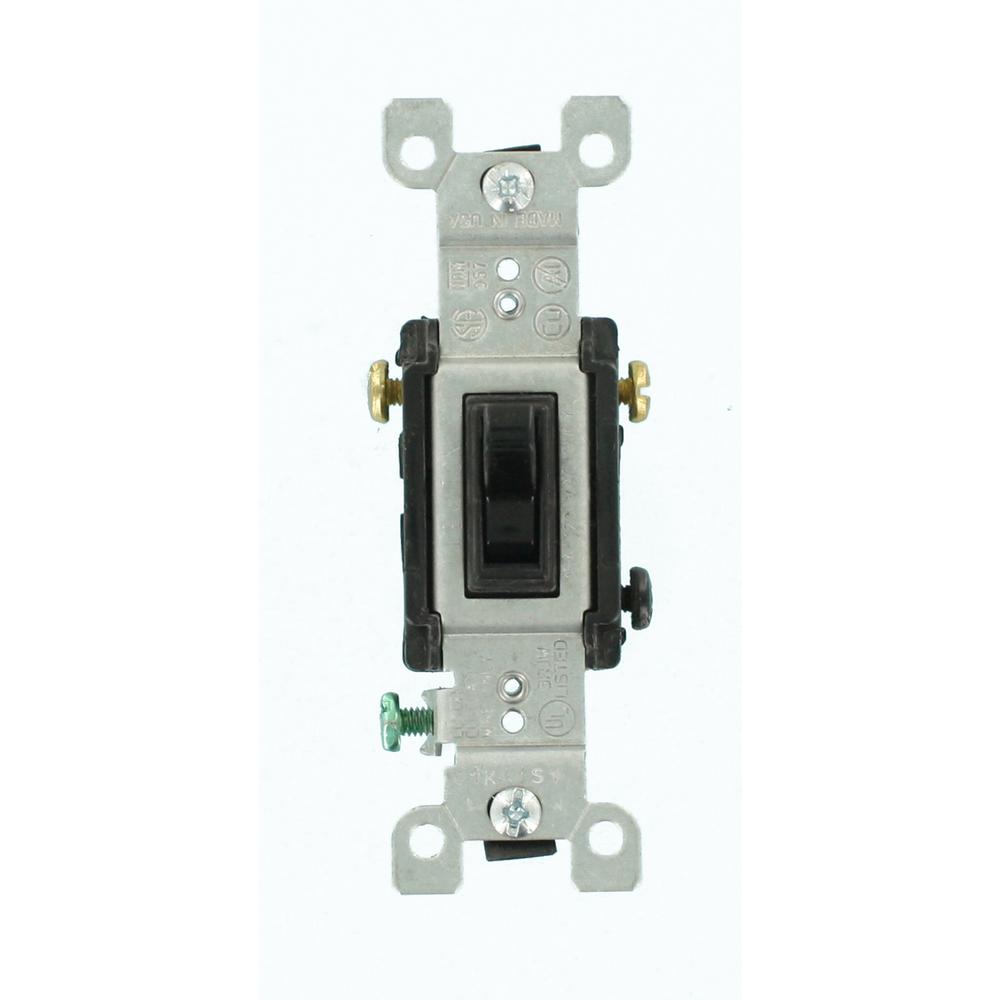
On the power coming in from the panel you would connect that black wire to the one black screw. Observe the layout of the wires. The black wire from the circuit breaker panel gets attached to the black screw on the 3 way switch. If you look at each of the main connection screws on a 3 way switch you should have no problem in determining that one of the screws is distinctly different in color or one screw is darker than the others. The common screw of a 3 way switch is the odd color screw. The black wire from the new cable connects to the black hot wire in the fixture box and to one of the terminals on the single pole switch.
Two of the terminals are a light colorbronze or copper coloredand are called travelers. Hooking up a switch is the essence of simplicity. The single dark colored screw is known as the common terminal. Screws for crl and oak grigsby switches stainless steel phillips 6 32 x 58 as supplied with our crl and oak grigsby switches. The switch also has a green terminal. You connect all white wires together in each box.
A more positive way to identify a 3 way switch is to look at the body of the switch and count the number of screw terminals. This wire is sometimes red. The green or bare copper ground wire if the device has one attaches to the green screw terminal on the switch or to the electrical box. You should also see a green. And on the other switch you would connect the black wire coming from the light to that black screw. 4586 roundhead for tele installation on a flat control plate.
That one screw that stands out from the other 2 is the common screw connection. You connect the black wires in the electrical box to the switch terminals and the white wires to each other. The extra length also allows installation in a carved guitar top. The black and red wires from the white cable running between the switches get connected to either of the two brass screws on the switch. The black and red wires in that 143 wire would connect to the other two screws.


