Longer life may be found due to a stronger motor where as 120 volt motors may heat up more which may affect the over all lifespan of the motor. A repulsion electric motor is by definition a single phase motor which has a stator winding arranged for connection to the source of power and a rotor winding connected to a commutator.

Ac Dpdt Wiring Diagram Ladder Diagram Base Website Diagram
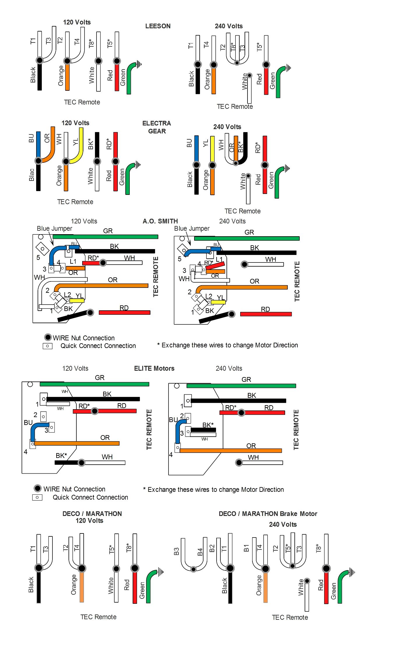
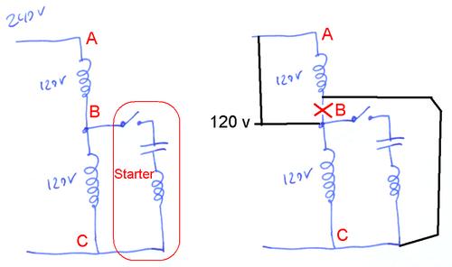
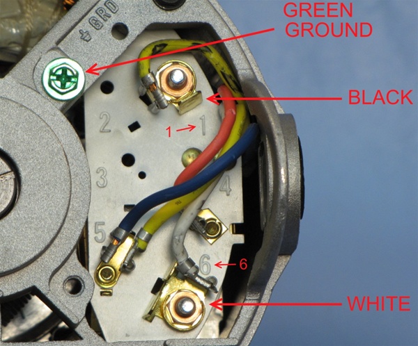
120 volt motor wiring diagram. 1040 x 1264. Reconfiguring between 240 and 120 volts is done the same way but the starter winding stays connected to one of the windings. Assortment of 240v motor wiring diagram single phase. A balanced electrical load which may save on electricity compared to an unbalanced electrical load. The usual aspects in a wiring diagram are ground power supply cord and link outcome devices switches resistors reasoning entrance lights etc. To read a wiring diagram first you need to know exactly what basic components are included in a wiring diagram and also which pictorial icons are used to represent them.
240v motor wiring diagram single phase single switch wiring diagram 110 single circuit diagrams wire center u2022 rh casiaroc co. Wiring a 120240 volt motor for 240 volts is as follows. Each component ought to be placed and linked to different parts in particular manner. Assortment of baldor single phase motor wiring diagram. If you dont have a wiring diagram and the motor is currently wired for 240 volts you can identify point b by the fact that it isnt connected to either power lead. This type of winding arrangement gives only half as much starting torque at 120 volts as on a 240 volt connection.
Click on the image to enlarge and then save it to your computer by right clicking on. Click on the image to enlarge and then save it. Stronger performance will definitely be noticed especially. If not the arrangement wont work as it should be. Single phase marathon motor wiring diagram wiring diagram 120 volt motor electric diagrams three phase basic marathon motors wiri. A list of electric signs and summaries could be found on the electrical icon web page.
Factory wired for 208 240 volts figure b it may also be wired for 120 volts check with the local power company to see if their power source is adequate for your requirements an mc 004. Ill dispense with the background issues unless you really want to hear the story and post my wiring diagram both for checking and for a better way to do it. Theres so many switch types and incomplete switch and motor information that its difficult to reach a solid conclusion for a wiring. Baldor single phase motor wiring diagram weg motor capacitor wiring diagrams schematics and baldor diagram in. Wiring diagram pics detail. Single phase motor wiring diagram with capacitor baldor single phase motor wiring diagram with capacitor single phase fan motor wiring diagram with capacitor single phase motor connection diagram with capacitor every electrical arrangement is made up of various unique pieces.
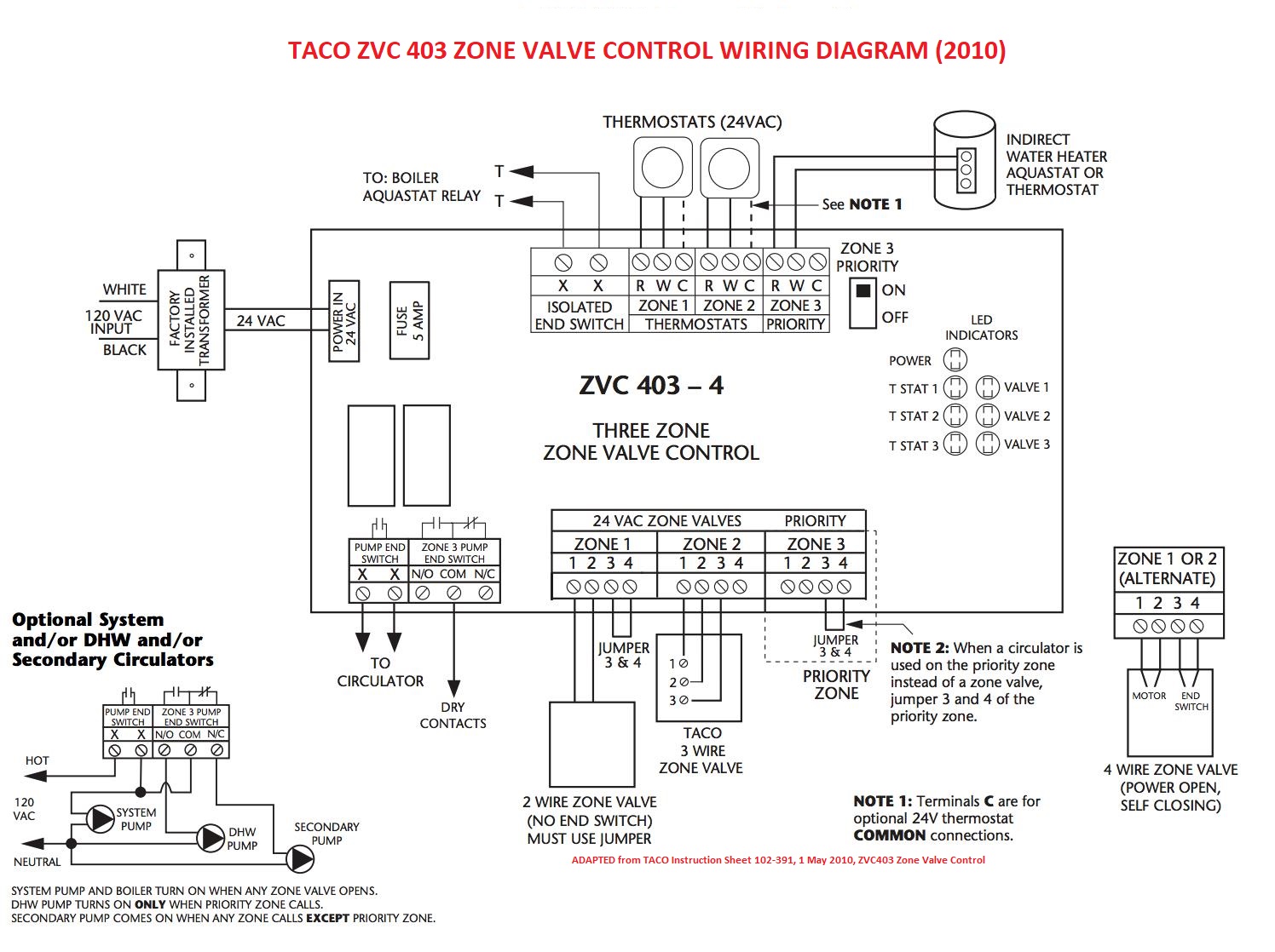
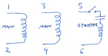
How to wire a motor starter a motor starter is a combination of devices to allow an induction motor to start run and stop according to commands by an operator or a controller typically an induction motor will run by a voltage of 230 volt or 460 volt 3 phase 60 hz in usa and be controlled by a control. 240 volt motors will have a stronger start compared to a 120 volt motor. The advantages of a 240 volt motor. Single phase marathon motor wiring diagram fancy electric motor wiring diagram single phase 47 about remodel with three weg 3 for motors. Wiring diagram pictures detail. So instead the starter winding in these motors is always a 120 volt winding and the motors two 120 volt windings are used as an autotransformer to make the 120 volts for the starter winding.
Gallery of 120 Volt Motor Wiring Diagram