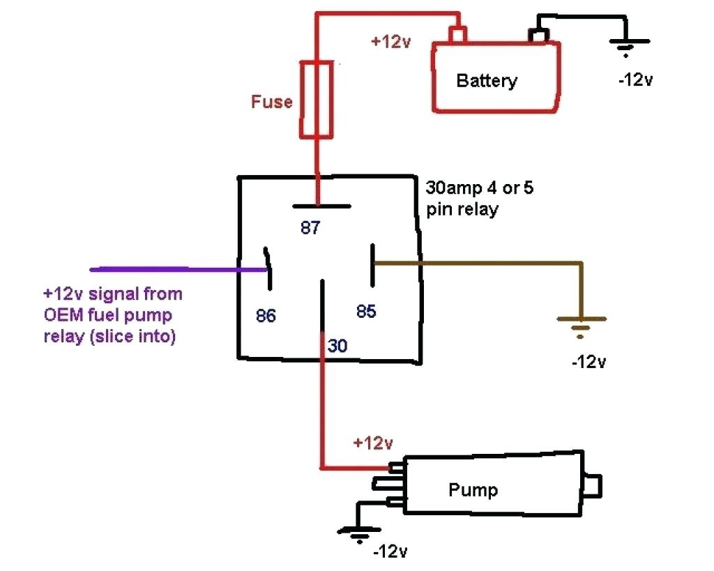
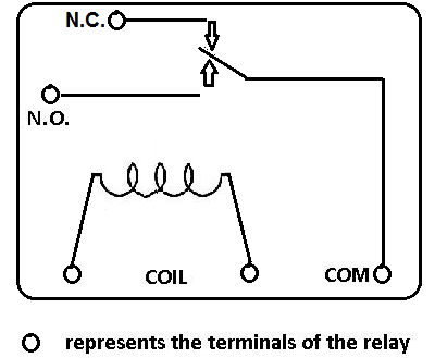
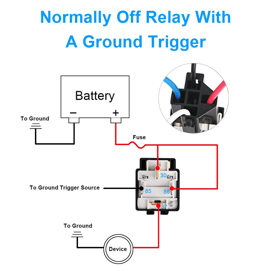
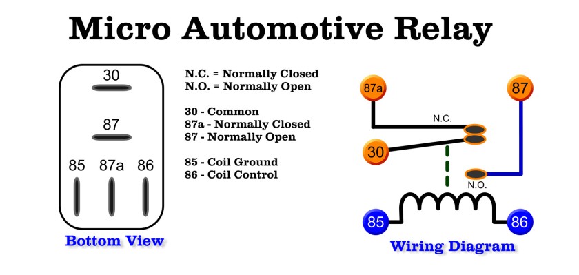
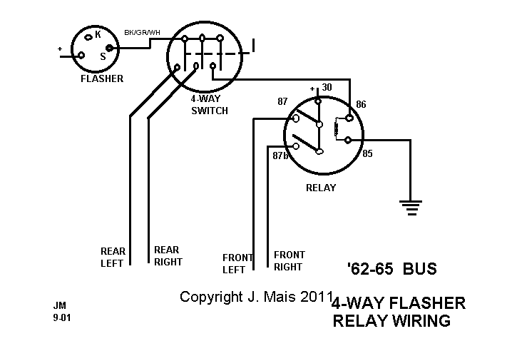
Free download with regard to 12v 30 amp relay wiring diagram by admin from the thousand pictures on the web about 12v 30 amp relay wiring diagram we selects the top choices together with ideal resolution only for you all and now this pictures is usually considered one of photographs series in our greatest. 4x4 and off road forum inside relay 4 pin wiring diagram image size 640 x 480 px and to view image details please click the image.
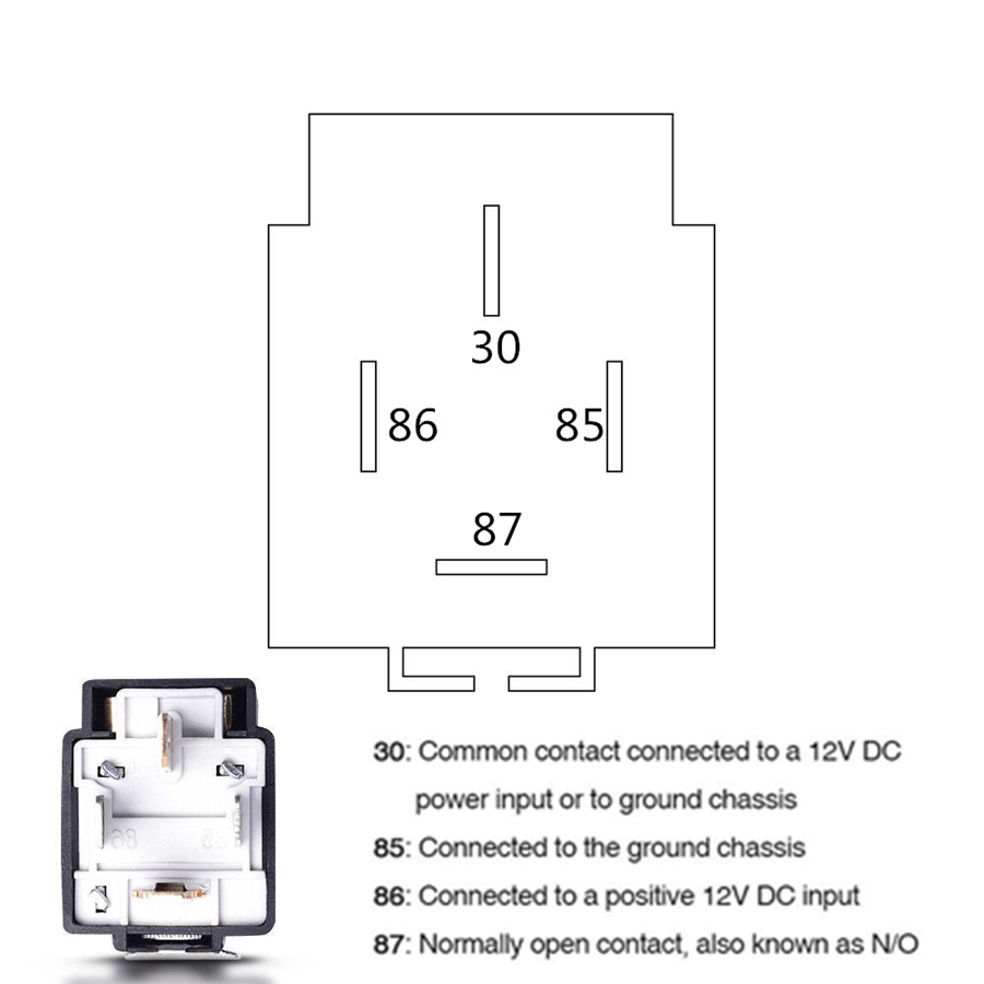
Details About 6pack 12v 30a Fuse Relay Switch Harness Set 4 Pin 14 Awg Hot Wires
12v 4 pin relay wiring diagram. 12v 5 pin relay wiring diagram is among the pics we discovered on the web from reputable. 12v 40a relay 4 pin wiring diagram. Clone kill relay wiring diagram. Here is a video on how you can test a relay with or without a diagram. This simple circuit uses the power feed to the headlight main beam bulb as the trigger to energise a relay. A wiring diagram is a simple visual depiction of the physical links and physical layout of an electrical system or circuit.
Relays are the integral component of any car wiring. Adding driving lights that come on with the headlight main beam. Its fully insulated and contains up to 7. Buggies gone wild golf cart forum modified golf carts big block talk. Denso parts are often used in japanese assembled cars including cars manufactured by renowned brands like toyota honda mitsubishi suzuki mazda daihatsu and several others. We hope this article can help in finding the information you need.
The high current circuit in this relay feeds power to the driving light bulb so every time headlight main beam is selected the coil is energised and the driving lights operate. Relays are used to bypass signal wire and directly supply current from battery thus your car wiring remains safe from heating up and burning due to the load of heavy components. 12 volt wiring diagram best 12v relay pin 5 and roc grp org in hvac fan relay wiring diagram download 12 volt relay wiring diagram download unique 1 volt relay inspiration best for wiring diagram just what is a wiring diagram. So use the right size wire. Headlight relay wiring diagram the above circuit is a way to use existing headlight wiring to control 2 relays that can be placed close to the lights. The main power from the battery feeding the fuse and relays should be a nice large gauge wire as indicated.
The following diagrams show some common relay wiring schemes that use 4 pin iso mini relays. Ac motor diagram start relay diagram 4 pin relay diagram auto relay diagram dpdt relay diagram automotive relay diagram 12 volt relay wiring diagrams reverse polarity relay diagram 7gfbcxdominik suessde. Here is a picture gallery about relay 4 pin wiring diagram complete with the description of the image please find the image you need. Relay diagrams pirate4x4. Wiring diagram for a 4 pin relay wiring diagram is a simplified agreeable pictorial representation of an electrical circuitit shows the components of the circuit as simplified shapes and the capacity and signal connections with the devices. 12 volt 4 pin relay wiring diagrams within 12v 5 pin relay wiring diagram image size 983 x 612 px image source.
It shows just how the electrical wires are adjoined and also could also reveal where components and components could be connected to the system. Example relay wiring schemes. The relay features a plastic housing with mounting tab for easy installation. No car wiring can be complete without these. This caused the headlights not to work properly. Denso relay 4 pin wiring diagram.
Here is a picture gallery about 12v 5 pin relay wiring diagram complete with the description of the image please find the image you need. Read relay diagram. Clone engine swaps. If you buy 7x6 inch led headlights or 4x6 headlight and your car socket is not standard h4 to 3 pin adapter is a must.


