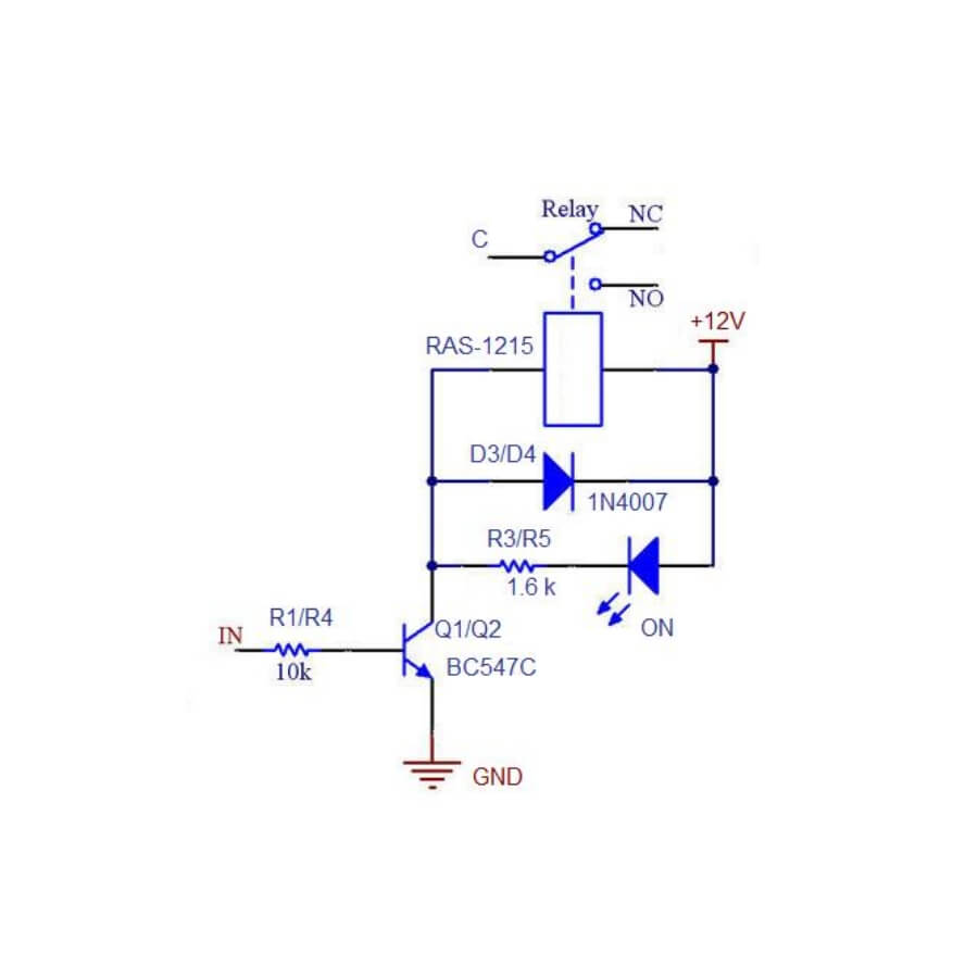
A 1kω resistor a 100kω variable resistor and another 1kω resistor are connected in series between the supply and ground. 3 powerstroke glow plug relay wiring diagram glow plug relay wiring diagram golf mk3 wiring diagram database.

Automotive Relay Diagram Diagram Circuit Relay 5 Pin
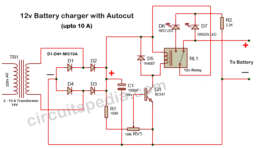
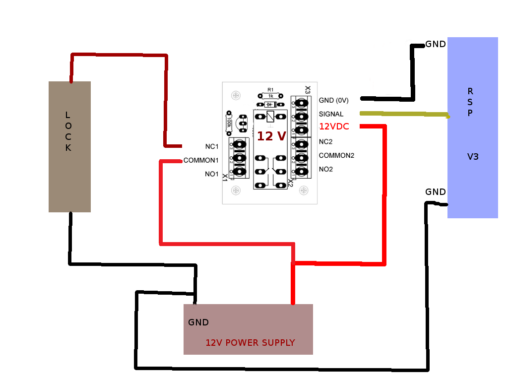
12v relay circuit diagram. The circuit can be used in the place of 12v mechanical relays. The alarm is a generic alarm and the golf is a vacuum type requiring a positive lock and unlock extended pulse. This is the current carrying capacity of the high current circuits and is normally between 25a and 40a however it is sometimes shown as a dual rating on changeover relays eg. The circuit will also serve for variety of other purposes for example it can also be use as an isolator for your microcontroler and arduino projects if you are driving motors etc. Typically 12v for passenger vehicles and small craft but also available in 6v for older vehicles and 24v for commercial applications both auto and marine. Working of the circuit is very simple when an input signal is.
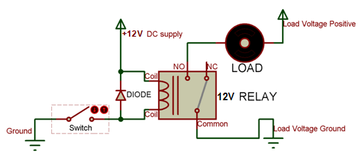
Here is a very useful circuit of a 12v dc solid state relay. An iron core is surrounded by a control coil. For switching we are using a transistor as a switching device. The above diagram is for relay triggering circuit. Fast switching speed triggered from wide range of voltages minimum trigger voltage is only 3v dc reliability noise less etc. 100 kω pot 1.
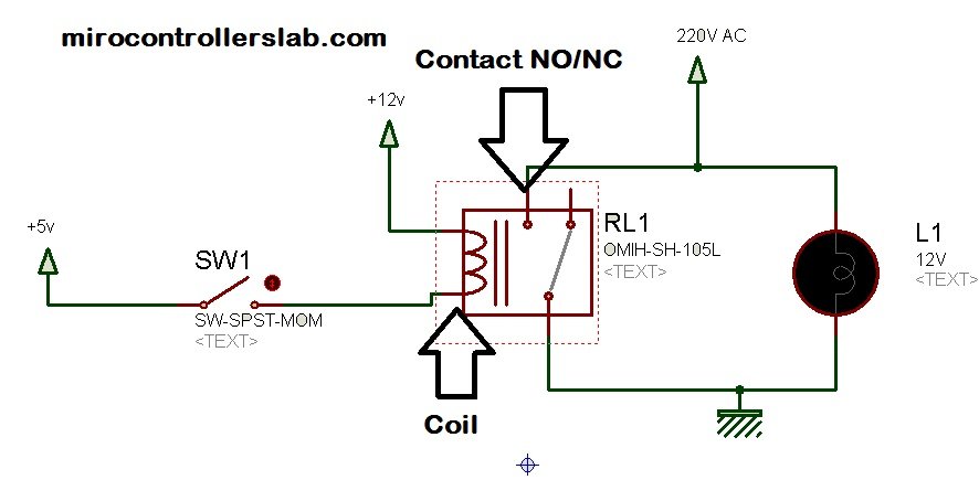
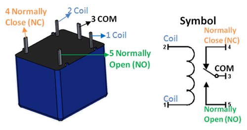
It reveals the components of the circuit as simplified shapes and also the power and signal connections in between the tools. 12v relay connection diagram read our guide to relays found in vehicle electrical systems. The top and bottom pins on the left are the relay coil pins. Since the relay has 12v trigger voltage we have used a 12v dc supply to one end of the coil and the other end to ground through a switch. 1n4728a 33v zener 1. 0l 16v tddi diesel engine d6ba 115bhp 140k miles 1013 for sale.
The middle pin is the common pin. You can also notice a diode connected across the coil of the relay this diode is called the. When current starts flowing through the control coil the electromagnet starts energizing and thus intensifies the magnetic field. Select a relay diagram or choose from the list below. The terminals are coil coil com and no and nc. The diagram shows an inner section diagram of a relay.
12v 3 amp power supply circuit diagram. 100µf 25v 1. 12v relay 1. New starter for ford b600 b700 b800 school bus caterpillar 3208 1985 1989 8c3596. The wiper terminal of the. The bottom right pin is the normally closed switched pin.
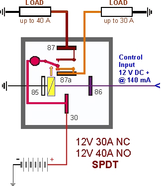
If you need a relay diagram that is not included in the 76 relay wiring diagrams shown below please search our forums or post a request for a new relay diagram in our relay forum. The operating voltage of the coil and high current circuits. The top right pin is the normally opened switched pin. Single pole double throw spdt relay diagram. In the case of dual ratings the normally closed circuit is the lower of the. Assortment of 12 volt relay wiring diagram.
The square relay pinout shows how the relay socket is configured for wiring. Dozens of the most popular 12v relay wiring diagrams created for our site and members all in one place. 1000µf 25v 1. 76 relay diagrams available relay. Circuit design of time delay relay. The last circuit.
Thus the upper contact arm starts to be attracted to the lower fixed arm and thus closes the contacts causing a short circuit for the power to the. The wiper of the variable resistor is connected to the positive terminal of a 1000µf capacitor. As shown the power source is given to the electromagnet through a control switch and through contacts to the load. A wiring diagram is a simplified traditional pictorial depiction of an electrical circuit. If i run 24 volts to the bed across the 12v inputs ill be drawing 16a and get 384 watts of heating power.
Gallery of 12v Relay Circuit Diagram