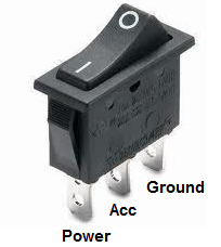
Pin 1 is where the rocker switch receives the input power. Spst toggle switch singe position single throw a spst switch is a simple on off switch.
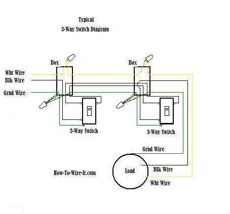
Wiring A 3 Way Switch
3 pin switch wiring diagram. A dpdt toggle switch has 6 terminals. Collection of 3 pin led flasher relay wiring diagram. This translates into the following model in a real life rocker switch. Sep 15 2015 this pin was discovered by bill cain. With these diagrams below it will take the guess work out of wiring. Pin 3 is where the switch is either connected to ground or left open.
This might seem intimidating but it does not have to be. This wiring diagram is impotent because by using this wiring connection a person can easily switch off the 3 pin socket or can easily switch on by using the circuit breaker. We will now go over the wiring diagram of a dpdt toggle switch. Illuminated rocker switch wiring. 3 way switch wiring diagram. Note if terminal 3 ground was not connected the switch would still operate the fan but you would not get illumination.
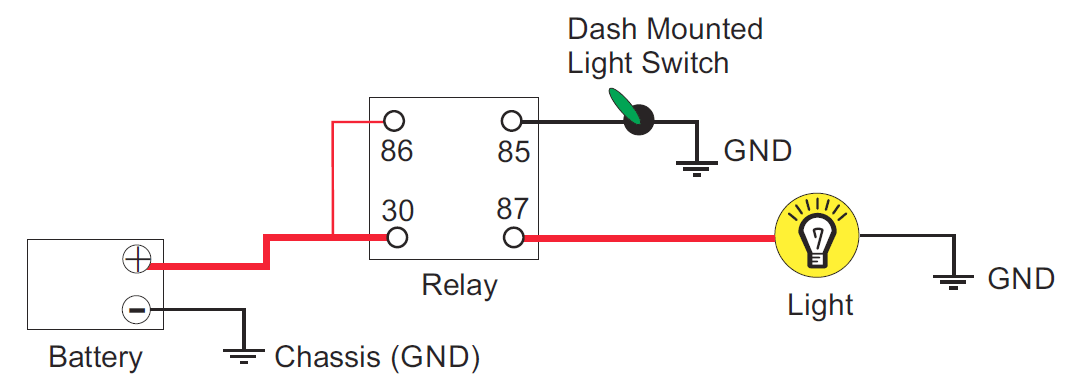
Here is an example of how you might wire up an auxiliary fan. Pick the diagram that is most like the scenario you are in and see if you can wire your switch. Terminals 3 and 4 represent the toggle switch. Relay uses and wiring. 3 way switch wiring diagrams. One is for input the other.
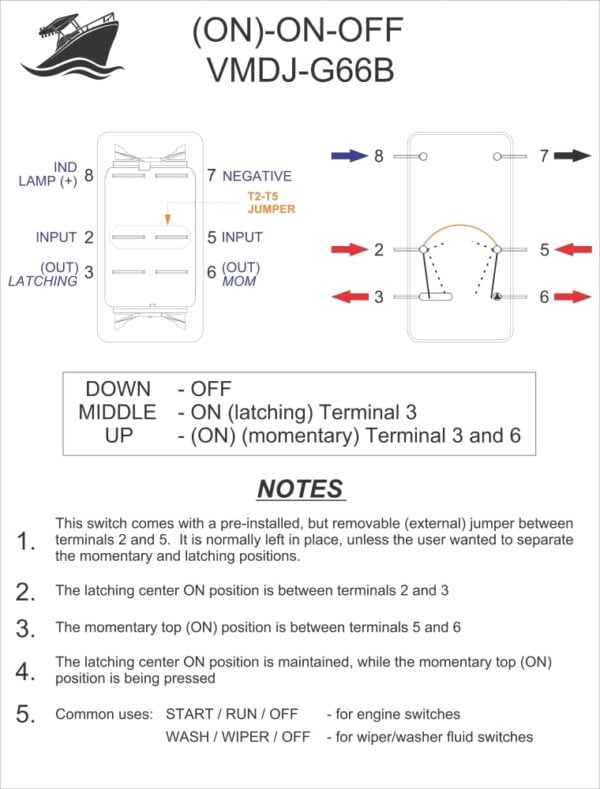
Note most switches will not illuminate if they are on the ground side of the accessory. The wiring diagram to the right will show how to wire and power this 12v 20amp on off on 3 way carling contura rocker switch. It reveals the elements of the circuit as streamlined forms and the power and also signal links between the devices. Discover and save your own pins on pinterest. These terminals receive the power necessary to drive the loads on terminals 1 and 5 and 2 and 6. Pin 2 is where the accessory that the switch is going to turn on is connected.
Or these terminals can be ignored for non backlit switch banks. If you have any doubts go to a professional. Sep 15 2015 this pin was discovered by bill cain. Improper wiring can damage your vehicles electrical system or cause a fire. A wiring diagram generally provides details regarding the relative placement and also plan of gadgets and terminals on the tools in order to help in building or servicing the gadget. A wiring diagram is a simplified conventional photographic depiction of an electric circuit.
How to install led bed lights fun diy project duration. 3 way switch wiring diagrams. How to wire an led toggle switch on off 3 prong rocker switch 2020 duration. Switched 3 pin socket or how to control a 3 pin socket from a circuit breaker. Take a closer look at a 3 way switch wiring diagram. Discover and save your own pins on pinterest.
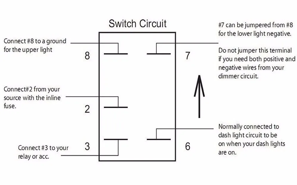
Below is the schematic diagram of the wiring for connecting a dpdt toggle switch. When wiring this switch you can choose if youd like to illuminate it because of the independent lamp attached to terminals 8 and 7. They typically have two terminals. Note this is just an illustration of how the switch works. Below is a pictorial representation of the schematic diagram.
