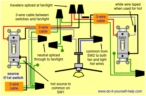
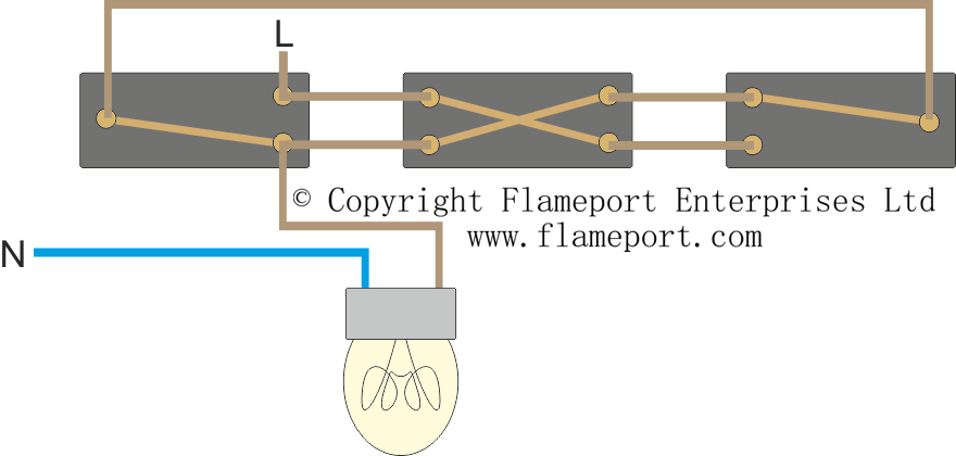
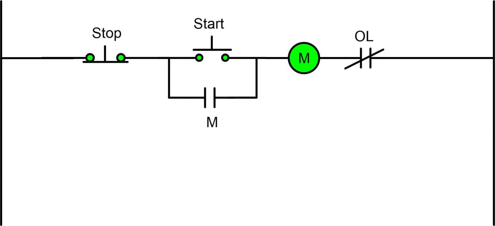
In this diagram the electrical source is at the first switch and the. This is a start stop push button control schematic which includes contactor m overload relay control transformer and push buttons.

Two Wire Inductive Proximity Sensors The Universal Donor
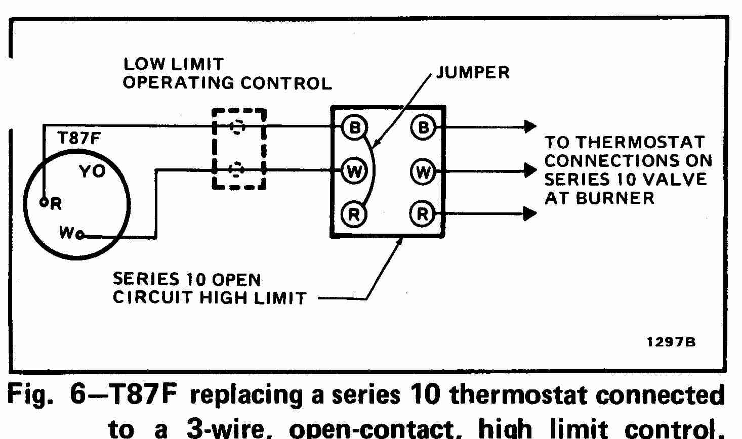
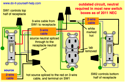
3 wire circuit diagram. 208v single phase and 208v 3 phase oem panels pertaining to 3 wire 220v wiring diagram image size 486 x 342 px and to view image details please click the image. A wiring diagram is a streamlined standard photographic depiction of an electric circuit. This wiring is commonly used in a 20 amp kitchen circuit where two appliance feeds are needed such as for a refrigerator and a microwave in the same location. All three way switch and 2 way switch wiring diagrams have the same basic components. Three way switch wiring with light middle. Bathroom electrical wiring fully explained photos and wiring diagrams for bathroom electrical wiring with code requirements for most new or remodel projects.
Turn the power off at circuit breaker. 3 way switch wiring with. See image below for an example of 3 wire control being used to pull in a contactor to start a 3 phase motor. With these diagrams below it will take the guess work out of wiring. If you are trying to troubleshoot a 3 way switch operation then you will need to identify the function of each wire. Wiring diagram for dual outlets.
Kitchen electric oven installation with a typical 240 volt electric circuit with 3 wire and 4 wire configurations. It reveals the elements of the circuit as streamlined shapes as well as the power and signal links in between the gadgets. The first step in any electrical project is to make sure there is no power going to the circuit you plan to be working on. The contactor contains large load contacts that are intend to handle large amount of current. 3 way switch wiring diagrams wiring diagram 3 way switch with light at the end. Pick the diagram that is most like the scenario you are in and see if you can wire your switch.
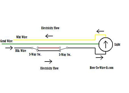
3 way switch wiring diagram. Control wiring 3 wire control start stop circuit the most common use of 3 wire control is a startstop control. Wires consisting of a line a load a neutral a pair of travelers and two 3 way switches. The source in this circuit is at the first switch and the light fixture is. Here 3 wire cable is run from a double pole circuit breaker providing an independent 120 volts to two sets of multiple outlets. The wiring diagram for connecting thee phase motor to the supply along with control wiring is shown in figure below.
Basic 3 way switch diagram how to wire 3 way light switch step by step. The neutral wire from the circuit is shared by both sets. This might seem intimidating but it does not have to be. Honestly we also have been noticed that 3 wire 220v wiring diagram is being one of the most popular subject at this moment. Variety of e bike controller wiring diagram. Components of 3 way switch wiring.
So that we attempted to get some good 3 wire 220v wiring diagram photo to suit your needs. Take a closer look at a 3 way switch wiring diagram.


