Relay diagrams pirate4x4. Start by cutting the white wire and attaching it to the trailer frame.

Backup Camera Wiring Diagram 4 Pin Wiring Diagram
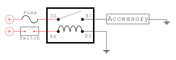
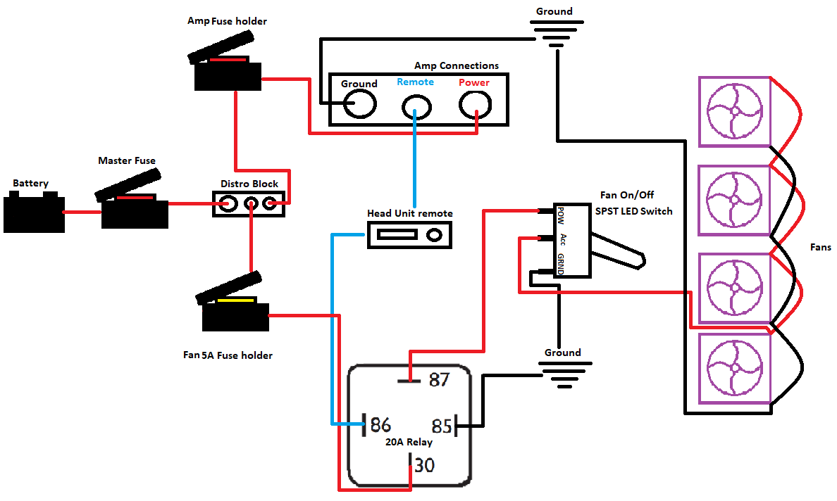
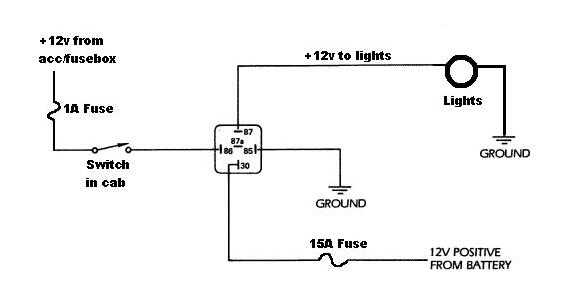
4 pin relay wiring diagram. This caused the headlights not to work properly. The main power from the battery feeding the fuse and relays should be a nice large gauge wire as indicated. When a relay contact is closed there is a closed contact when the relay is not energized. The relay features a plastic housing with mounting tab for easy installation. The wiring diagram is given below to help you wire it properly. Here is a picture gallery about relay 4 pin wiring diagram complete with the description of the image please find the image you need.
Each component ought to be set and connected with different parts in particular way. When a relay contact is open the relay is not energized. In either case applying electrical current to the contacts will change their state. Here is a video on how you can test a relay with or without a diagram. This wiring method is fully compatible with any 4 pin denso relay starting with the serial number 156700 or look like the sample denso relays below. Find a suitable entry point in the trailer for laying the wires.
Otherwise the structure wont function as it ought to be. You must check the trailer manual to see if the wiring is correct but normally the white wire is called the ground wire while the brown wire is used for tail lights. Assortment of 12 volt relay wiring diagram. Relays are generally used to switch smaller currents in a control circuit and do not. Installing the 4 pin trailer wires. 4x4 and off road forum inside relay 4 pin wiring diagram image size 640 x 480 px and to view image details please click the image.
12 volt relay wiring diagram bosch relay wiring diagram 5 pole fresh 5 pin relay wiring diagram inspirational pin relay wiring. So use the right size wire. Relays switches are used to open and close circuits electromechanically or electronically. The rest of the wires are wired from below. Its fully insulated and contains up to 7. Headlight relay wiring diagram the above circuit is a way to use existing headlight wiring to control 2 relays that can be placed close to the lights.
This should be a position that protects the wires. 12v 40a relay 4 pin wiring diagram. Here we look at relay switch pin diagram and the different kinds of relay switches. Click on the image to enlarge and then save it to your computer by right. Wiring a denso relay is extremely simple. Yellow and green are for left and right turns and braking.
You just need to buy a separate relay harness to install it properly. 4 prong relay wiring diagram 4 pin flasher relay wiring diagram 4 pin relay wiring diagram 24v 4 pin relay wiring diagram fan every electrical structure consists of various unique pieces. Free download with regard to 12v 30 amp relay wiring diagram by admin from the thousand pictures on the web about 12v 30 amp relay wiring diagram we selects the top choices together with ideal resolution only for you all and now this pictures is usually considered one of photographs series in our greatest. If you buy 7x6 inch led headlights or 4x6 headlight and your car socket is not standard h4 to 3 pin adapter is a must.


