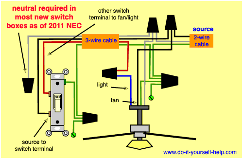
4 wire ceiling fan capacitor wiring diagram new unique wiring size. Ceiling fan capacitor wiring diagram natebird me at 3 wire.
Ceiling Fan Has Only One Speed The Home Depot Community
4 wire ceiling fan capacitor wiring diagram. The outcomes of the gathering are published on this site. Whatever you are we aim to bring the content that matches just what you are looking for. You may originate from an internet search engine after that discover this site. Please right click on the image and save the photograph. Take a look at ceiling fan capacitor connection wiring this color is not the same for all fan manufacturing company. Look the capacitor connection how the color of wire is used in fans output.
You may be capable to learn precisely once the assignments should be finished which makes it much easier for you personally to correctly manage your time and efforts. A wiring diagram is a streamlined standard pictorial depiction of an electrical circuit. Alaska ceiling fan wire diagram data wiring diagrams. This topic is a lot of individuals looking on the internet as a result we gather images from different reliable sources as well as recognize in their area. In the above diagram i shown ac supply and i connect the neutral wire to motor winding common winding point and the phase hot wire connect to the one way switch and form switch connect to the motor main winding and capacitor all wires of capacitance which is 45 uf 4 uf and 6 micro farad. Therefore we have the method to determine it with a digital multi meter.
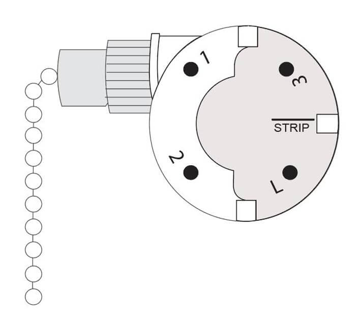
Wellborn collection of 4 wire ceiling fan switch wiring diagram. 3 sd switch wiring diagram trusted diagrams. This is the 4 wire ceiling fan capacitor wiring diagram new unique wiring of a photo i get directly from the ceiling fan capacitor wiring collection. Wiring a ceiling fan with light how to wire and. Ceiling fan wiring diagram light switch house electrical. Next find the wire that makes the fan run the slowest and connect that wire to 3.
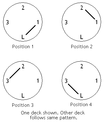
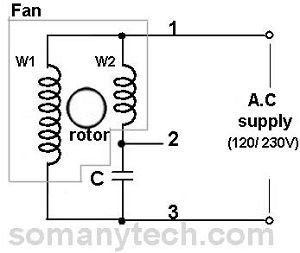
Ceiling fan capacitor connection internal wiring of a fan. In the above ceiling fan capacitor wiring diagram i shown a symbol diagram of fan motor winding in which i shown start run and common wiresi connect the common wire connection with one connection connector and then i connect the run wire to the other wire connector as i shown in above diagram with blue color line. 3 way fan light switch ceiling and. 800 x 600 px source. Converting an existing ceiling fan to a remote control. Below is the circuit diagram of split phase induction motor in a ceiling fan clearly showing a capacitor connected in series with the starting winding auxiliary winding.
Can i connect the blue and black hot wires to single red in my. And you can see that speed selector switch on low direction and when its switch move on the 5 uf the ceiling fan will be on med speed and on 6 micro farad the speed will be high. Wadoy cbb61 ceiling fan capacitor 4 wire for new tech vac 5060hz 5uf 5uf zing ear zes6 3 speed 4 wire ceiling fan switch use for ceiling fans. February 28 2019 by larry a. You can save this pic file to your personal device. Switch that was supposed to replace a broken switch in a hunter ceiling fanonce you identify the speed tap wire that makes the fan run the fastest connect that wire to 1 on the new switch.
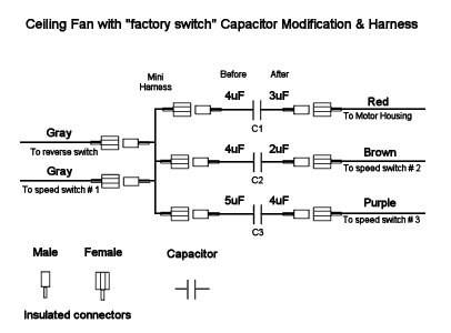
This kind of image 4 wire ceiling fan. 44 lovely installing a ceiling fan from 3 wire to 2. We also have some more pics connected to ceiling fan capacitor wiring please see the photo gallery below click one of the pictures then the picture will be displayed large as shown above. As i shown in the above ceiling an 3 wire capacitor diagram that red. Before go in details about why a capacitor is connected in series with the auxiliary winding let is know what will happen if there is no capacitor in a ceiling fan. 3 way switch ceiling fan to capacitor wiring diagram best wiring 5 wire ceiling fan capacitor wiring diagram.
Furthermore wiring diagram provides you with time body by which the tasks are to be finished. Images of ceiling fan capacitor wiring diagram hunter simple 5 wire ceiling fan capacitor wiring diagram. It reveals the elements of the circuit as simplified shapes and the power and signal connections between the tools.


