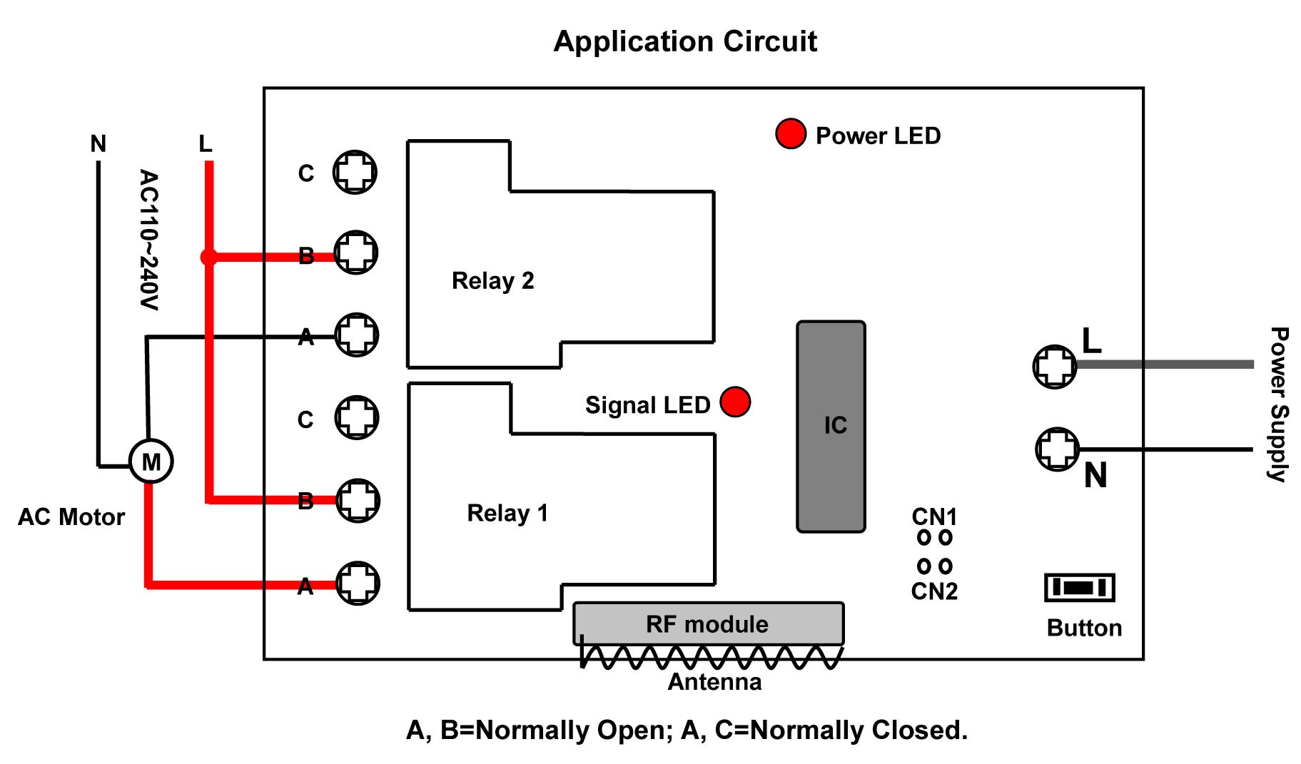
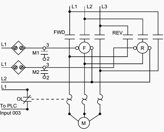
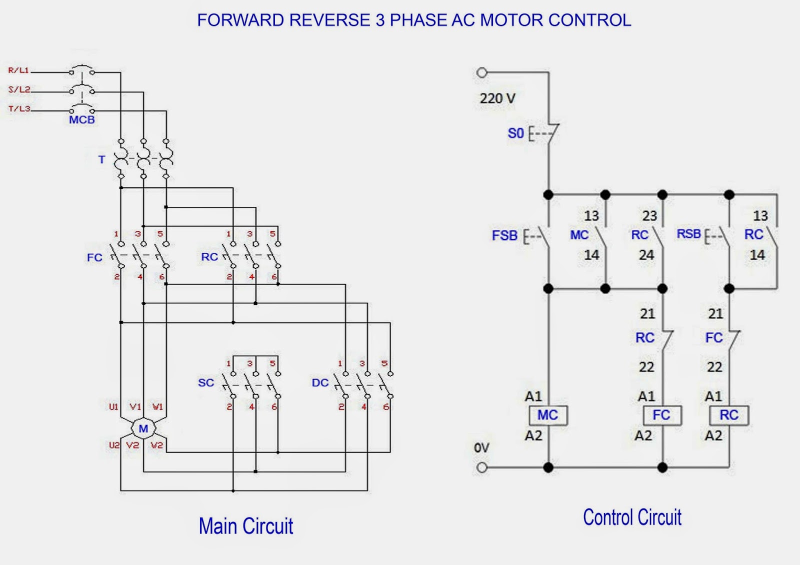
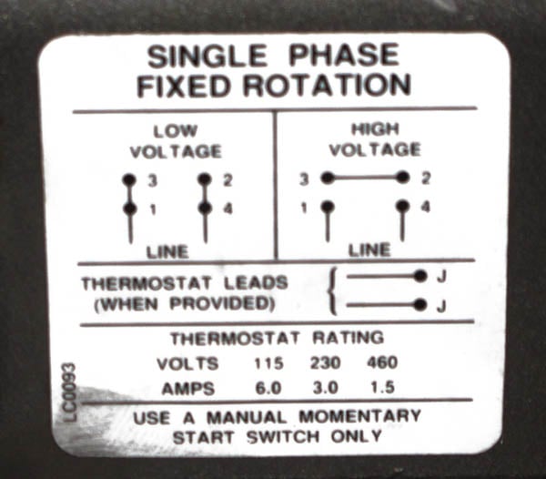
With the main windings connected in parallel the line voltage is. In general a phase is eliminated remaining two are connected as in the diagram above.

110 Single Phase Motor Wiring Diagrams Wiring Diagram
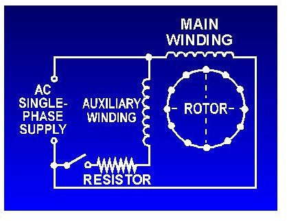
Ac motor wiring diagram single phase. Starting winding is also known. This motor has two identical main windings arranged for either series or parallel connections. Split phase single value capacitor electric motor dual voltage type. This video will show you how to connect a single phase motor with two capacitors. The other thing that you will get a circuit diagram would be traces. Amazon sells motor start capacitors.
A motor with a start and run capacitor and a start and run coil. Capacitor start capacitor run induction motors are single phase induction motors that have a capacitor in the start winding and in the run winding as shown in figure 12 and 13 wiring diagram. You can consider capacitors value mounted in similar engines single phase. These tips can be used on most electric motor brands such as weg baldor. This type of motor is designed to provide strong starting torque and strong running for applications such as large water pumps. For all other single phase wiring diagrams refer to the manufacturers data on the motor diagram dd6 diagram dd7 m 1 ln e diagram dd8 ln e l1 l2 l3 sc z1 u2 z2 u1 cap thermal contacts tb some standard frame induction motor diagrams have been included for ease of presentation pgs ocdedv gamma series d 1417 diags er 1 2 4 5 ocd magnetic starter 30a 120240v coils this magnetic starter is a 3 phase full voltage across the line starter with the coil factory wired for 208 240 volts.
A circuit is usually composed by many components. Split phase single value capacitor electric motor dual voltage type. You will not have the same power and starting torque otherwise you can use an inverter. The first component is symbol that indicate electrical element in the circuit. There are two winding inside the ceiling fan known as starting winding and running winding. Vasu babu paleti 3 years ago.
Generally the ceiling fan motors are split phase single phase ac motors. In this video jamie shows you how to read a wiring diagram and the basics of hooking up an electric air compressor motor. There are two things which are going to be present in any single phase motor wiring diagram with capacitor. A wiring diagram is a simplified conventional pictorial representation of an electrical circuit. Variety of single phase motor wiring diagram forward reverse. 3ø wiring diagrams 1ø wiring diagrams diagram er9 m 3 1 5 9 3 7 11 low speed high speed u1 v1 w1 w2 u2 v2 tk tk thermal overloads two speed stardelta motor switch m 3 0 10v 20v 415v ac 4 20ma outp uts diagram ic2 m 1 240v ac 0 10v outp ut diagram ic3 m 1 0 10v 4 20ma 240v ac outp uts these diagrams are current at the time of publication.
It reveals the components of the circuit as simplified forms as well as the power as well as signal links in between the tools.


.png)

