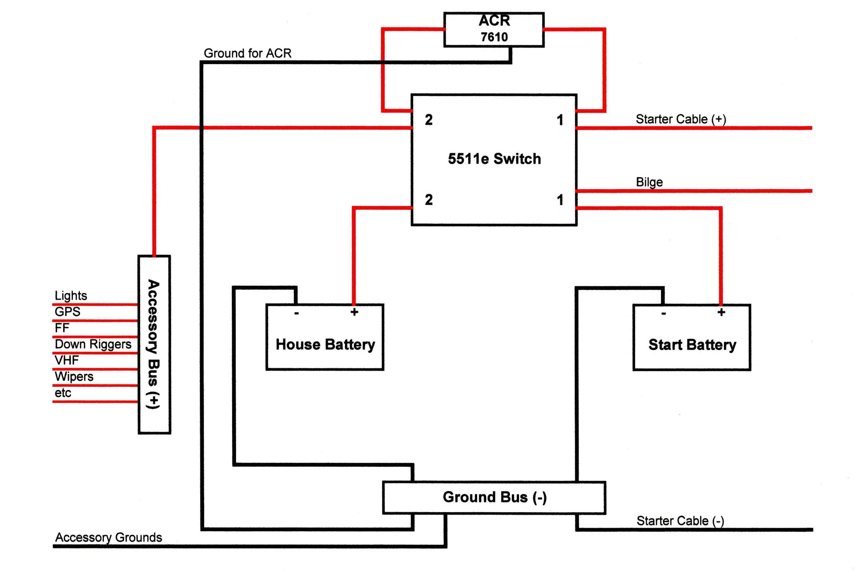
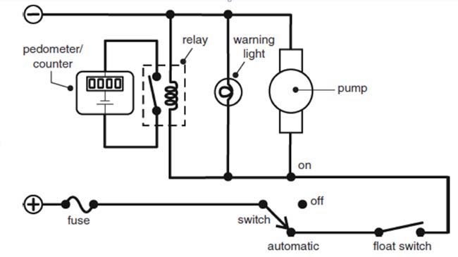
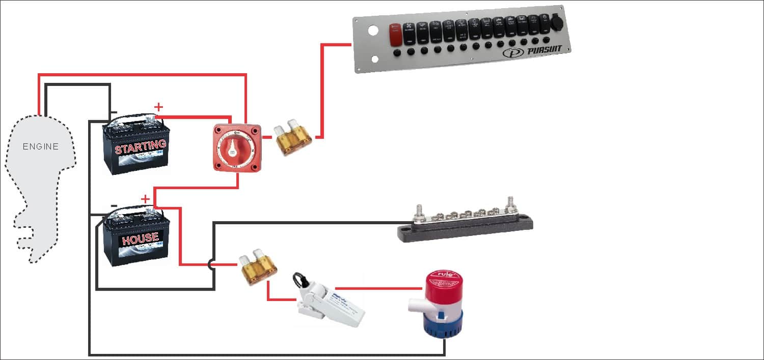
It shows the elements of the circuit as simplified forms and the power and signal connections between the tools. Save now on new oem triton boat parts and accessories at great lakes skipper.

Dpdt8term On Carling Toggle Switch Wiring Diagram Toggle
Boat light switch wiring diagram. 3 your use of red and black wires is incorrect. A wiring diagram is a streamlined conventional photographic depiction of an electrical circuit. Negative lines go to ground wherever you find it thats not on the switch 2 the diagram does not show where on the switch each wire goes. The red wires to the. Red is the positive feed. 1999 triton tr 21 boat light switch wiring diagram.
In this video wiring guide we show how to wire a 7 terminal vjd1 d66b rocker switch to operate a boats navigation and anchor lights. In this extremely common configuration a single switch is. Your diagram does not show that. Wiring a boat eric steele 2020 06 23t020124 04. 2004 triton t 21 dash panel help. Questions about your triton trailer.
Assortment of perko marine battery switch wiring diagram. Notice on the wiring diagram that of the 10 prongs spade connectors called termianls on the back four 4 make the rocker switch lights function while the remaining six are used for the electromechanical switching contacts. It reveals the parts of the circuit as simplified shapes as well as the power and signal links between the devices. I need a simple wiring diagram for a small outboard boat to wire up the lights and few other things but no one seems to have one. Push pull nav light switches just like the three six and seven terminal toggle or rocker switches must be wired correctly. Home how to wiring a boat.
Term blocks bus bars. Variety of pontoon boat wiring schematic. A wiring diagram is a simplified conventional photographic representation of an electrical circuit. This switch body does have two isolated negative inputs t9 and t7 for each lamp or led in the switch. A wiring diagram is a simplified conventional photographic representation of an electrical circuit. Only one red wire should exit the battery or preferably the fuse panel into the switch.
Meters and gauges.


