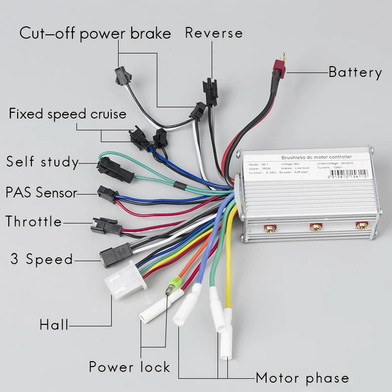
Three thicker phase wires. Greentime haute qualité 36v 250w e bike brushless contrôleur de moteur bldc pilote de moteurprofitez de super offres de la livraison gratuite de la protection de lacheteur et dun retour simple des colis lorsque vous achetez en chine et dans le monde entier.
.png)
Blws6523 Ip65 Rated Sealed Brushless Motors
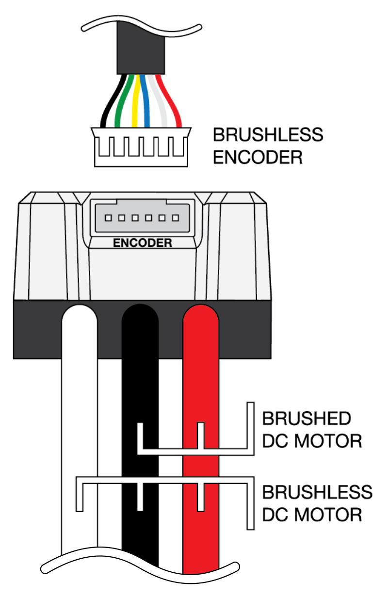
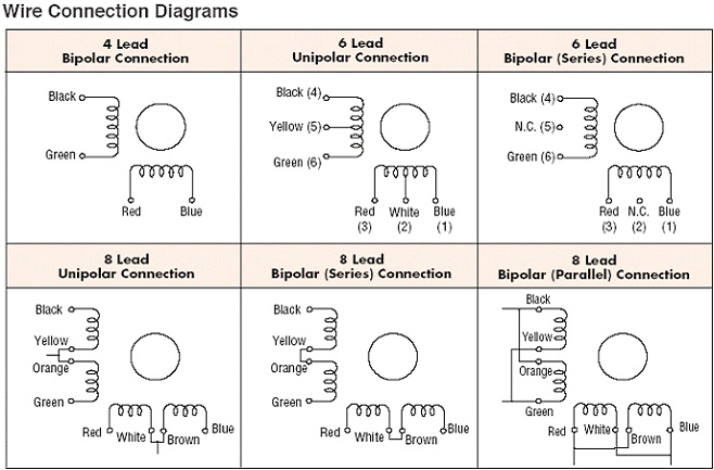
Brushless motor wiring colors. Power goes both ways in all the wires changing the magnetism of the components in the motor and inducing the spin. This 3 phase wires are used to changed the current direction to motor so that the motor can run continuously in the same direction. For common brushless dc motor it has hall sensors so the total motor wires is 8. The most common color coding for the hall power is red positive black ground. The hall supply wires will branch off and go to all three sensors. Its counter intuitive and motoresc builders confuse things by having the wires color coded in the first place.
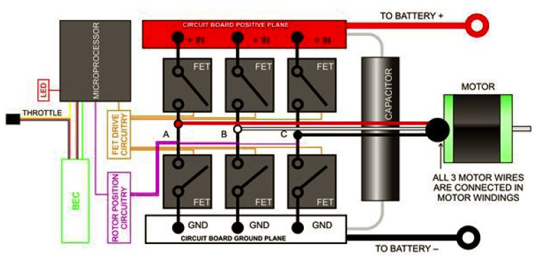
Brushless motor controller schematic the two most important electric motors are the ac induction motor and permit true brushless running the next dc motor improvement came in the form of a solid state speed control product brushless dc by an electronic circuit ordinarily bldc motors use hall effect devices hfd to sense rotor position and control the electronic drive of the motor however by monitoring arrow electronics panasonic industry and stmicroelectronics join forces to deliver iot. The brushless motors are ac alternating current. A quick explanation of the order of wires on a brushless motor. From a bldc controller we also can see 3 corresponding wiresuyellow vgreen wblue or ayellow bgreen cblue. Three thiner hall sensor wires. You will know each motor wire color and means.
If there are no black and red wires or it is not clear which are the power wires it may be necessary to open the motor and trace the wires going to the hall sensors. Power goes in one wire and comes out of the other.




.png)


