Rocker switches carling offers a wide array of full sized to miniature illuminated and non illuminated snap in rocker switches. Many of these switches though are quite flexible thought.
Carling V Series Rocker Switch Wiring Diagram H1 Wiring Diagram
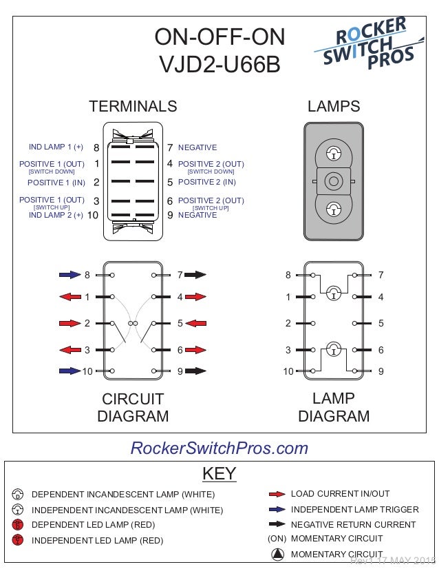
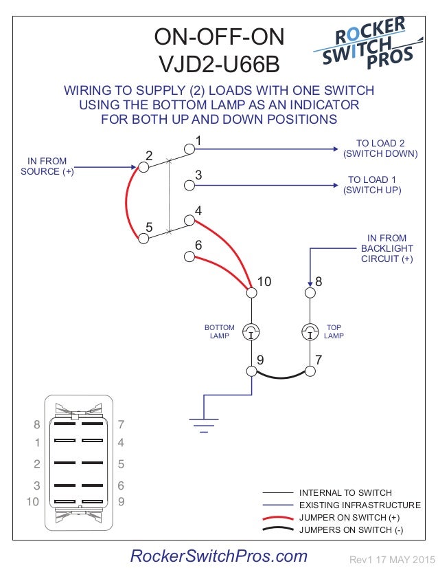
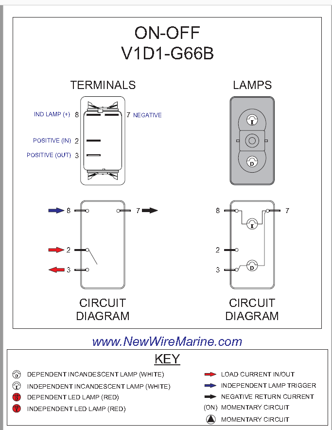
Carling rocker switch wiring. The first component is emblem that indicate electrical component in the circuit. There are just two things which are going to be present in any carling switch wiring diagram. With just a few small jumpers our switch selection can be used for a multitude of different functions. Assortment of carling technologies rocker switch wiring diagram. A wiring diagram generally provides info concerning the relative setting as well as plan of devices and terminals on the gadgets to assist in building or servicing the tool. We stock all the common marine labels printed or etched onto the switch itself.
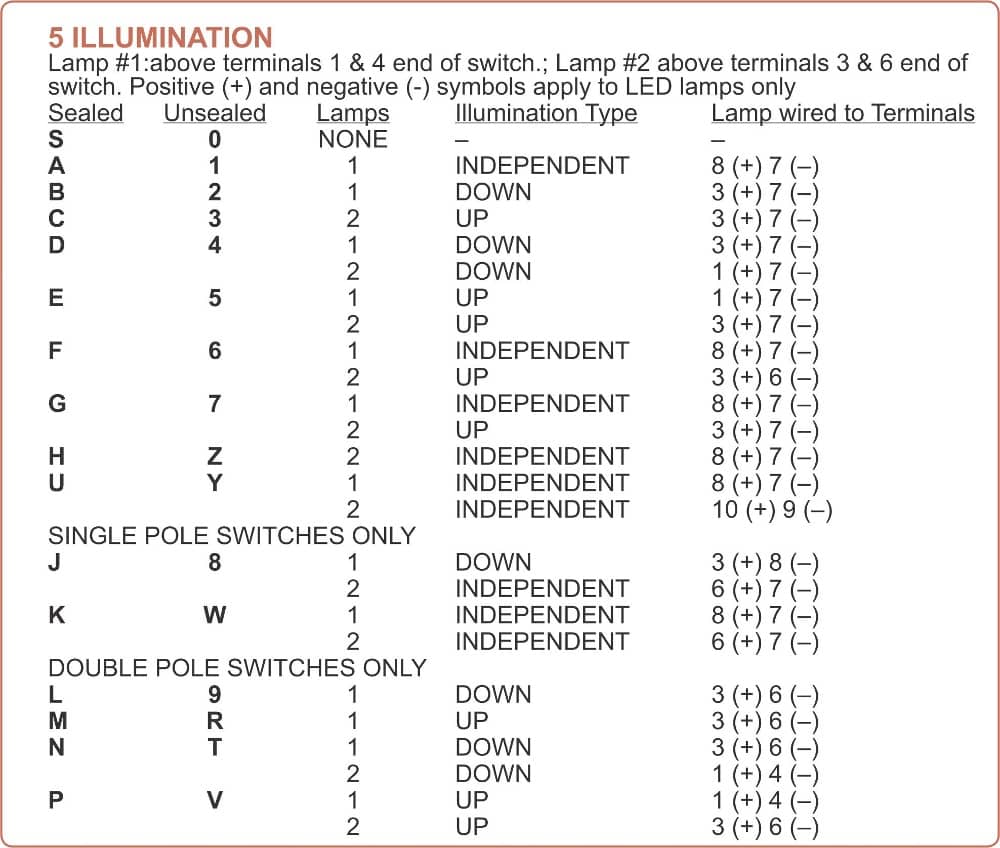
They offer a variety of nylon and metal toggle styles as well as illuminated toggles. Our marine rocker switches are perfect for 12vdc power distribution on your boat. Standard switch wiring diagrams carling technologies inc. With independent lamp circuit only 3. Certifications include ul csa tuv vde and more. Ranging from 1 to 4 poles4 va to 20 amp with many styles of solid colored translucent two color visi rockers.
Each part should be set and linked to other parts in particular way. Certifications include ul csa vde. It is off at the bottom on in the center and momentary on at the top. The vmdj is a unique dpdt momentary rocker switch. Each of our carling rocker switch bodies have the generic wiring diagram loaded into that products own page see photo right. A circuit is usually composed by several components.
Several families of heavy duty toggle switches are available as well as a high temperature snap in toggle switch series. Contact terminal will make contact with switching lever isolated terminal does not make contact with switching lever contact terminal switch lever bulb notes. The wiring diagram below will demonstrate how to to wire and power this 12v 20amp on on off 3 way carling contura rocker switch. Carling bushing mount toggle switches range from 1 to 4 poles 1 to 20 amps. The other thing which you will locate a circuit diagram could be lines. We carry all genuine carling technologies switches.
Ranging from 1 to 4 poles4 va to 20 amp with many styles of solid colored translucent two color visi rockers. Carling switches wiring diagram 4 pin carling switch wiring diagram arb carling switch wiring diagram carling dpdt rocker switch wiring diagram every electric arrangement consists of various diverse pieces. With lighting sequences 10 20 30 4050 only. Carlings v series is the top of the line marine rocker switch. If not the arrangement wont function as it should be. It reveals the elements of the circuit as streamlined shapes and the power and signal connections between the gadgets.
Certifications include ul csa tuv vde and more. Carling offers a wide array of full sized to miniature illuminated and non illuminated snap in rocker switches. A wiring diagram is a simplified standard photographic depiction of an electrical circuit. With nbl bracket only 2. This rocker is perfect for an engine offrunstart switch.


