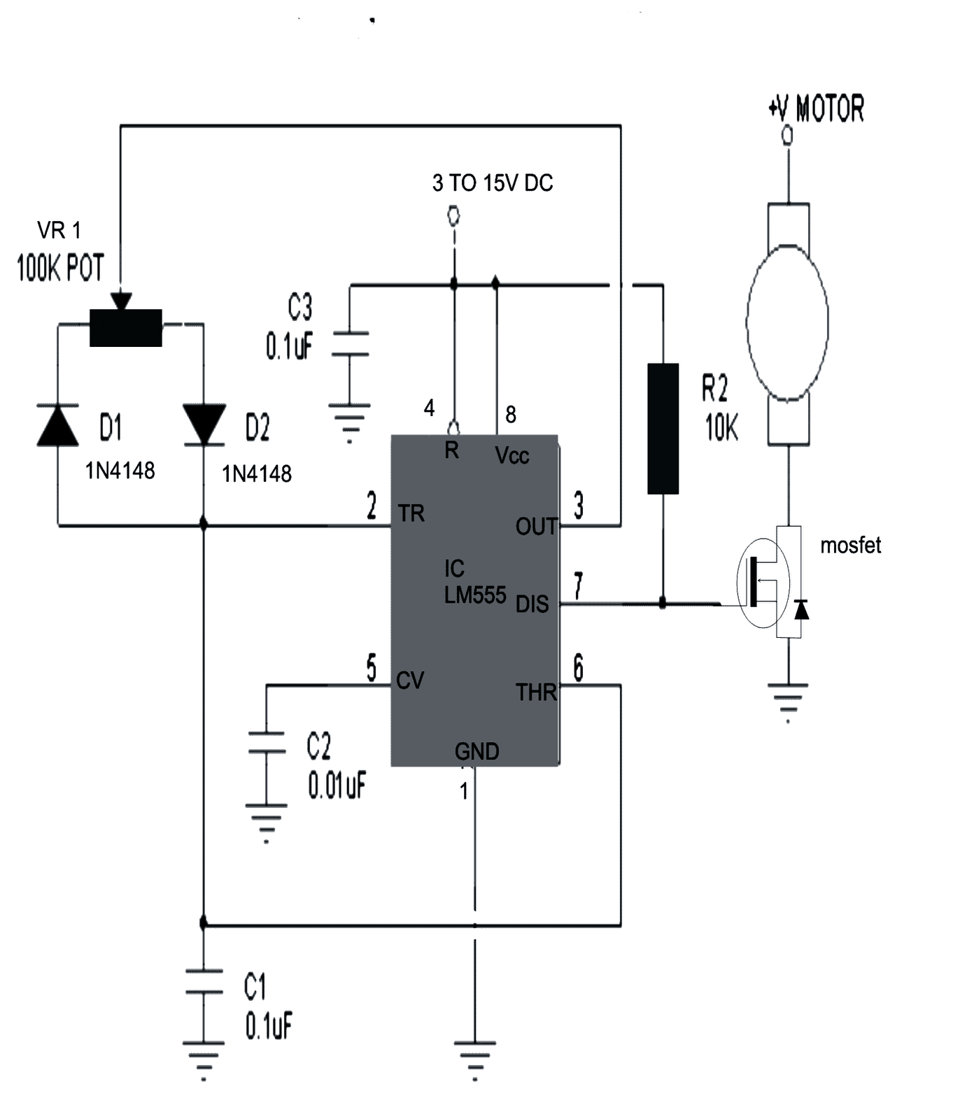
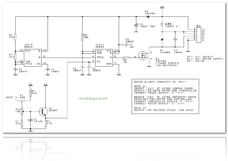
As can be seen the mosfet is rigged as a source follower or a common drain mode to learn more about this configuration you may refer to this post which discusses a bjt version nevertheless the working principle remains the same. Dc motor learning objectives.
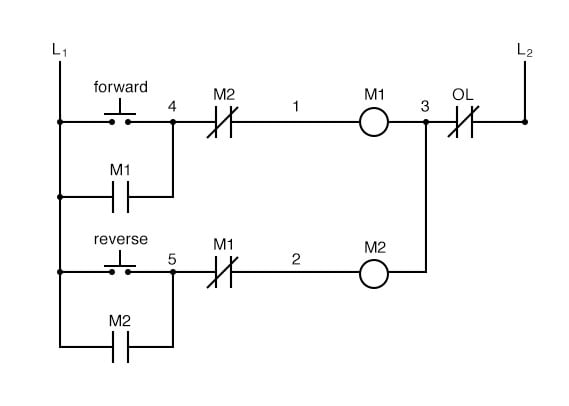
Motor Control Circuits Ladder Logic Electronics Textbook
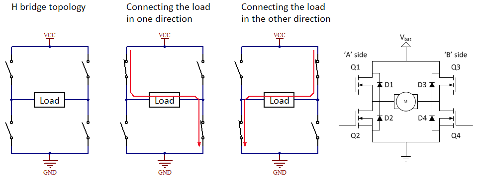
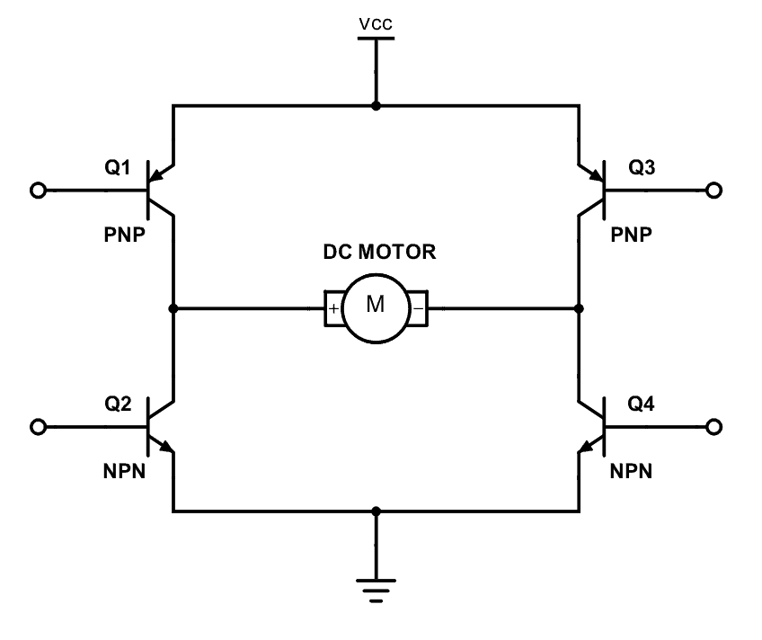
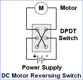
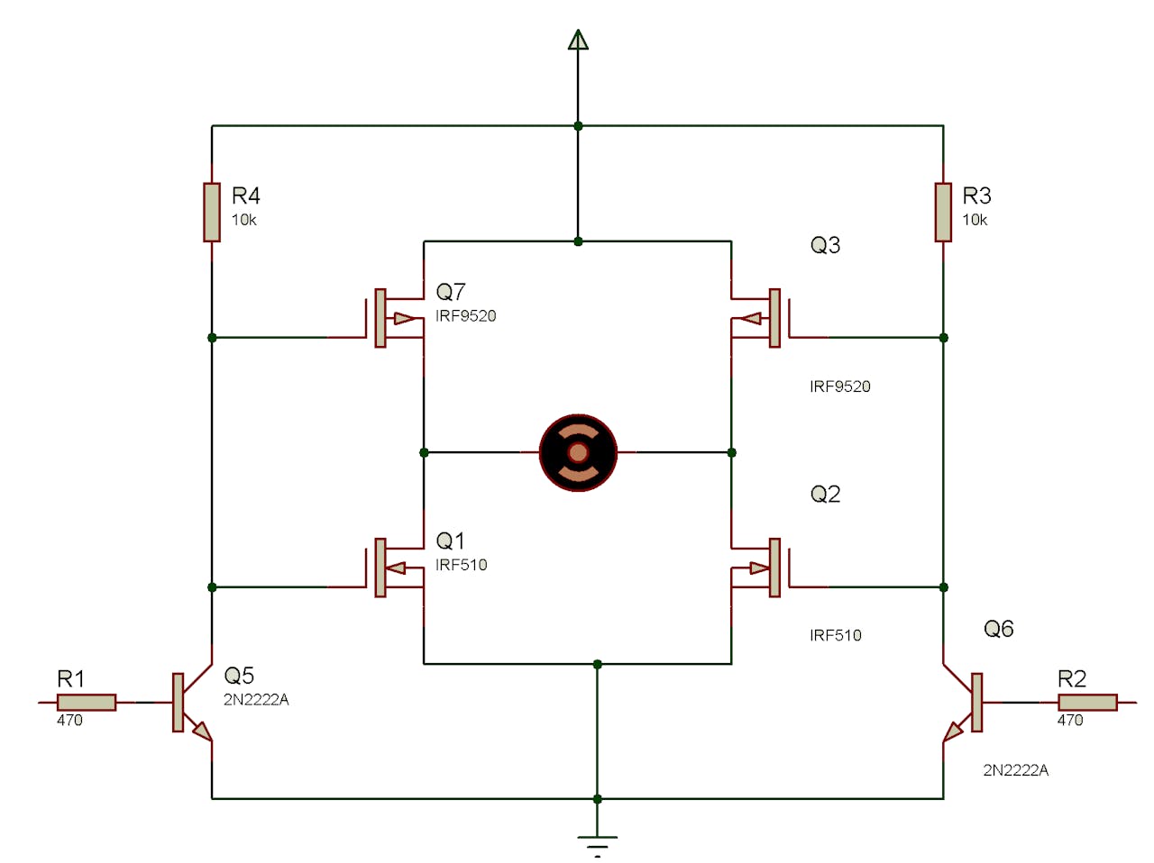
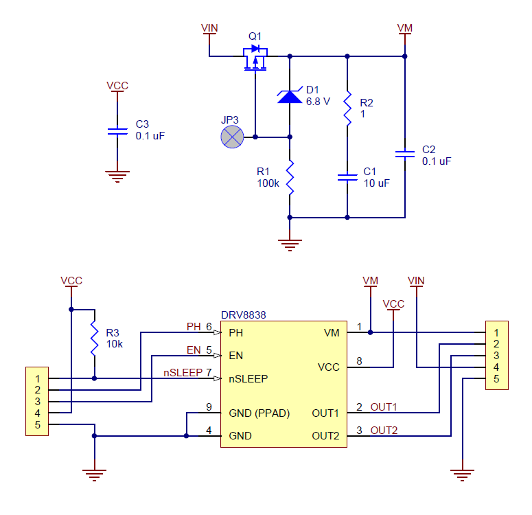
Dc motor reversing circuit schematics. Explain the role of a snubber diode. The dc motor is connected to the supply through dpdt double pole double through switch by changing the switch position we can get forward and. Implement a transistor circuit and arduino program for pwm control of the dc motor. In this website we already published about speed control of dc motor with timer ic here this circuit constructed for the basic motive to meet the forward reverse operation of dc motor with speed control. Relays control forward stop and reverse action and the motor cannot be switched from forward to reverse unless the stop switch is pressed first. Basic dc motor circuits.
A dc motor reversing circuit using non latching push button switches. Relays control forward stop and reverse action and the motor cannot be switched from forward to reverse unless the stop switch is pressed first. Until the stop button is used. In the above dc motor controller design the pot adjustment creates a varying potential difference across the gate of the mosfet and the source pin of the mosfet. Describe how pwm controls dc motor speed. This circuit has a built in safeguard against that condition.
Putting a motor straight into reverse would be quite dangerous because when running a motor develops a back emf voltage which would add to current flow in the opposite direction and probably cause arcing of the relay contacts. Living with the lab. Dc motor reversing with relay by circuit diagram a dc motor reversing circuit using non latching push button switches. Dc motor reversing circuit.

