Silent 100 design. Show results of subfolders.

Mf 7913 Potentiometer Wiring Diagram Fan Download Diagram
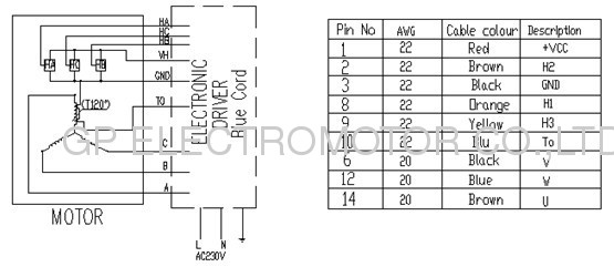
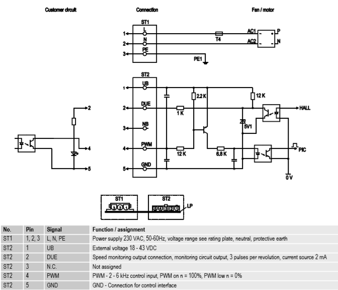
Ec motor wiring diagram. Compact scpd 3ph. The 3 control wires are not used. Simple and flexible for configuration of high efficiency fans. Ec motor wiring this publication contains supplemental wiring instructions for units incorporating ec motors. Star delta y δ 3 phase motor starting method by automatic star delta starter with timer. External rotor motors dc motors.
Read more history kruger products are licensed to. With this kind of an illustrative guidebook you will be able to troubleshoot stop and full your assignments with ease. Ams started trading late in 1994 with duncan burl at its helm. 3302007 32429 pm. Cfp cf series. For additional safety information refer to amca publication 410 96 safety practices for users and installers of industrial and commercial fans.
Ecm motor wiring diagram youll need an extensive expert and easy to know wiring diagram. Three phase motor power control wiring diagrams three phase motor connection schematic power and control wiring installation diagrams. Ec fans and motors with highest ef ciency. It shows the components of the circuit as simplified forms and also the power and also signal links between the gadgets. To select a fan an airflow and a static pres the search result be limited in additional selection criteria in the fan. Loren cook catalogs provide additional information describing the equipment fan performance available accessories and specification data.
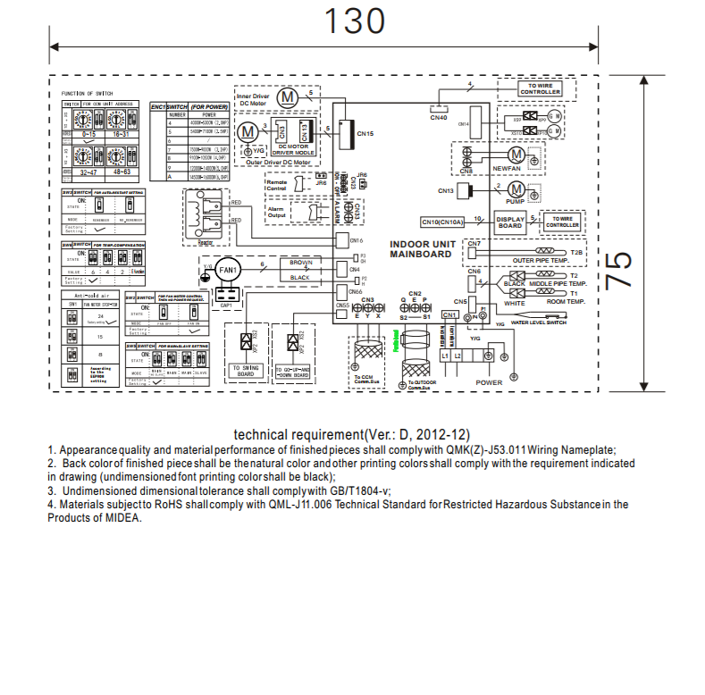
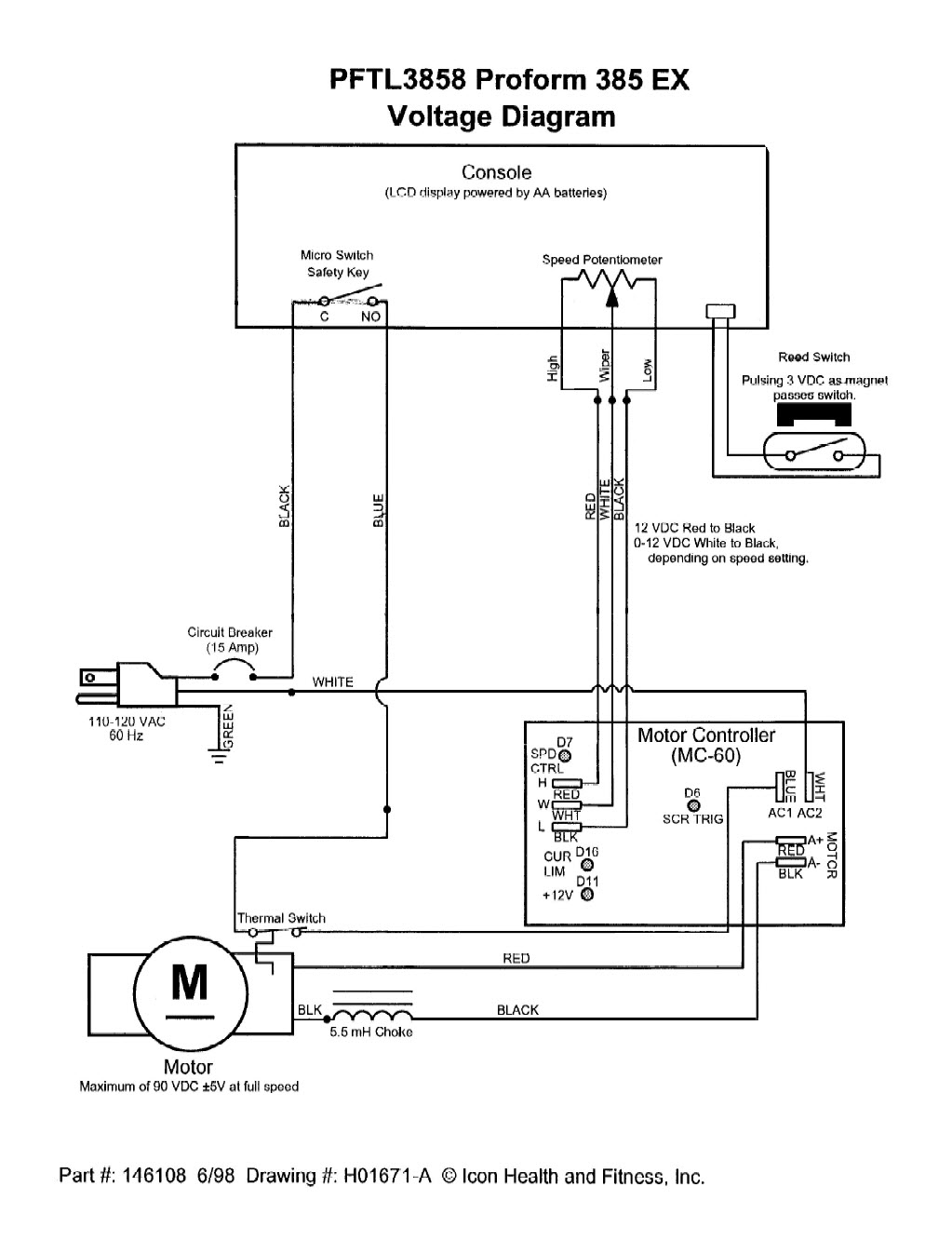
Output of wiring diagram graphic. 112 and 150 three phase motor wiring instructions this video is to demonstrate how to wire an ebm papst ec motor with a 150 frame size motor. A wiring diagram is a simplified standard photographic representation of an electric circuit. M3g074 motor single phase m3g084 motor single phase m3g112 motor 3 phase for single phase motor apply single phase supply as shown above. Safe area smokevent hazardous. 3ø wiring diagrams 1ø wiring diagrams diagram er9 m 3 1 5 9 3 7 11 low speed high speed u1 v1 w1 w2 u2 v2 tk tk thermal overloads two speed stardelta motor switch m 3 0 10v 20v 415v ac 4 20ma outp uts diagram ic2 m 1 240v ac 0 10v outp ut diagram ic3 m 1 0 10v 4 20ma 240v ac outp uts these diagrams are current at the time of publication.
Rm eci cn1003 emc standards interference emission en61000 6 3 interference immunity en61000 6 2 harmonics en61000 2 23 controller wiring diagrams fan wiring diagrams ac fans ac controllers ec fans ec controllers accessories wiring diagrams. Prior to installing the fan it is to be checked whether the safety zone as per en iso. Td silent and td series. Compact scpd mfb 1ph. Assortment of ebm papst motor wiring diagram. All of the.
Ec motor wiring diagrams potentiometer dial only see figure 6 motor features a potentiometer dial located on the side of the motor allowing the user to make necessary speed adjustments with a small flat tip screw driver. This will cover both how to connect. Standard frame motors. Not merely will it enable you to attain your desired results faster but in addition make the whole method simpler for everybody. The key to an intelligent fan control and adjustment of fans. Carefully read this publication prior to any installation or maintenance procedure.

