June 2009 370489g 01 multifunction rio ni r series multifunction rio user manual ni 781xr ni 783xr ni 784xr and ni 785xr devices r series. Injunction of two wires is generally indicated by black dot on the junction of 2 lines.

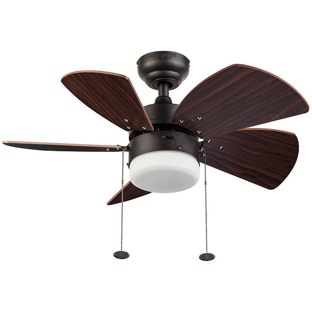
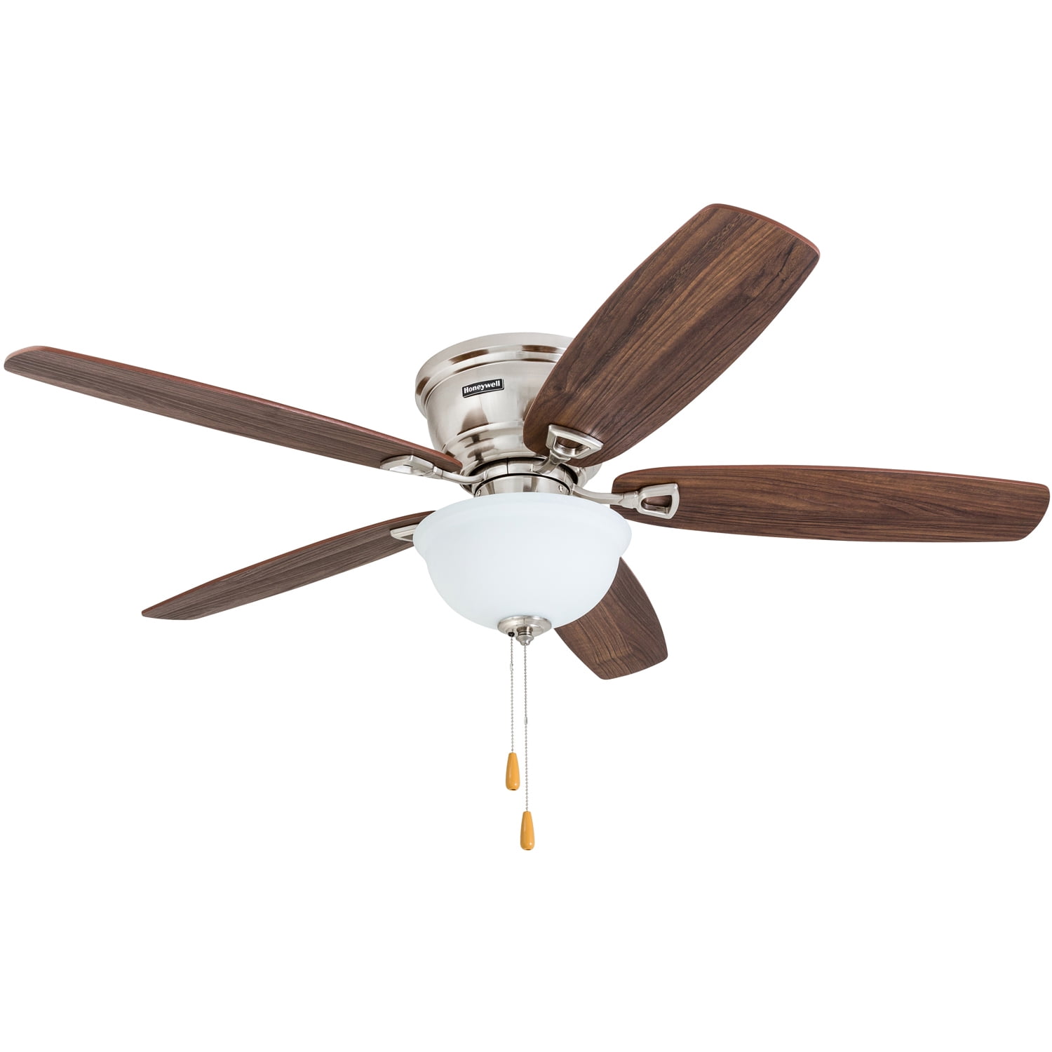
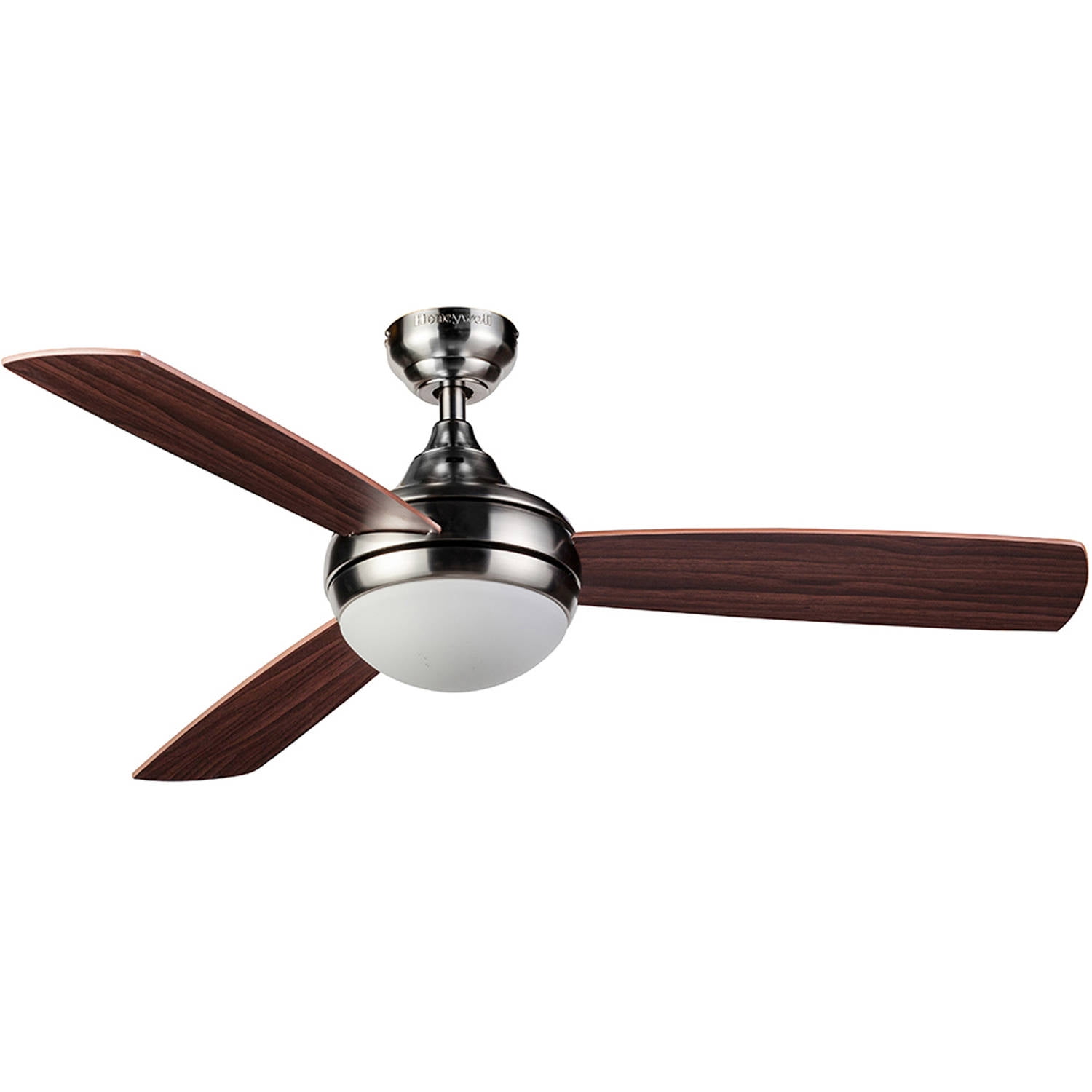
Honeywell Ceiling Fans 50600 01 Ocean Breeze Contemporary 30 Led Frosted Light Light Oak Satin Nickel Finish Blades White
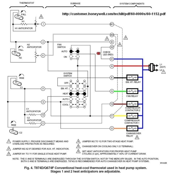
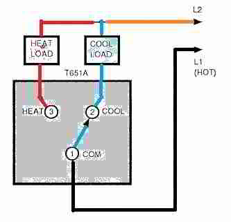
Honeywell ceiling fan wiring diagram. A wiring diagram is a streamlined standard pictorial representation of an electric circuit. It shows the elements of the circuit as streamlined forms as well as the power as well as signal connections in between the devices. After switching power off at circuit breaker remove ceiling fan canopy from the mounting bracket. The line voltage enters the switch outlet box and the hot wire will connect to every switch. Switch off the power at the circuit breaker before working on receiver or ceiling fan. The internet electrician.
Disconnect existing wiring between ceiling fan and supply at electrical junction box. Do not install in damp location or immerse into water. Wiring diagram for honeywell thermostat th3110d1008 new beautiful. Variety of 4 wire ceiling fan switch wiring diagram. However it does not imply connection between the cables. Occasionally the wires will cross.
Click on the image to enlarge and then save it to your computer by right clicking on the image. Switch hots and line neutral will connect to a 3 wire cable that travels to the fanlight outlet box in the ceiling. 4 wire ceiling fan switch wiring diagram 4 wire ceiling fan switch wiring diagram throughout carlplant best. Rio 54 ceiling fan honeywell code and ansinfpa 70 199 hire a qualified electrician or consult a do it yourself wiring handbook if you are unfamiliar with installing electrical wiring make sure the installation site you choose allows a minimum clearance of 7 ft 214 m from the blades ni r series multifunction rio user manual national. For indoor use only. Interconnecting cord courses may be revealed about where certain receptacles or fixtures have to be on a common circuit.
Get honeywell thermostat th3110d1008 wiring diagram download. This unit is to be used for the control of a ceiling fan and its electrical source must be ac 110120v 60hz. A wiring diagram generally offers info regarding the. Honeywell fan limit switch wiring diagram architectural circuitry representations reveal the approximate areas and affiliations of receptacles lights as well as long term electric solutions in a building. According to previous the lines at a 5 wire ceiling fan capacitor wiring diagram represents wires. Slide the receiver into the mounting bracket per fig1 being careful not to pinch the antenna wire.
The receiver will be inserted between the down rod. Do not use this remote with fans that have preinstalled. Adding a ceiling fan to a room is a simple diy wiring project but the addition of a remote control to a ceiling fan adds a greater level of difficulty to the wiring. Variety of honeywell thermostat th3110d1008 wiring diagram. Ceiling fan and light switch wiring diagram. Wiring a ceiling fan and light with two switches diagram wiring diagram is a simplified okay pictorial representation of an electrical circuitit shows the components of the circuit as simplified shapes and the gift and signal friends with the devices.
