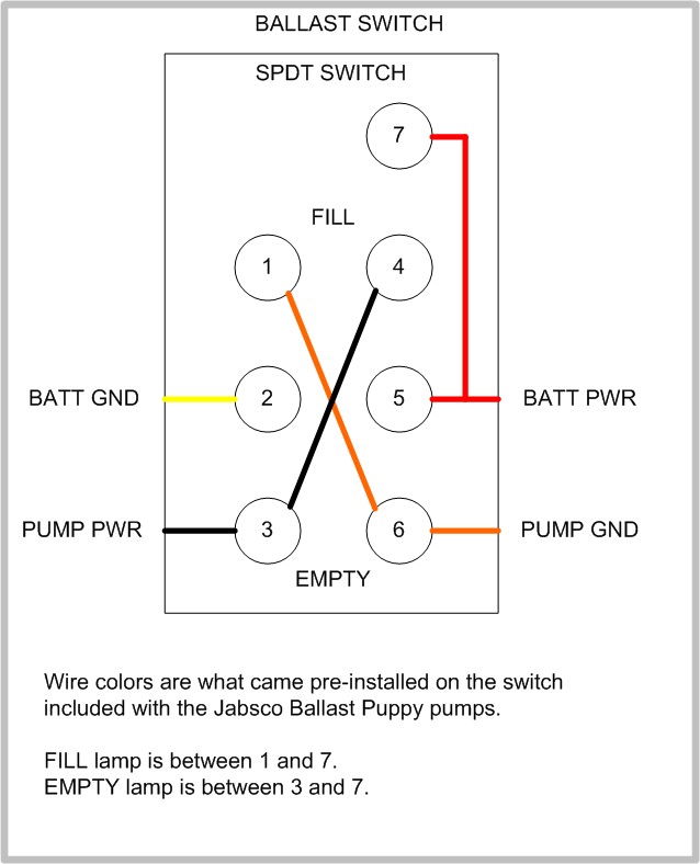
Collection of 6 pin toggle switch wiring diagram. At the end of the blue jumper attach another disconnect terminal.
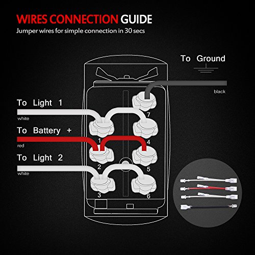
6 Pin Rocker Switch Wiring Diagram H1 Wiring Diagram
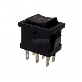
How to wire a 6 pin rocker switch. Plug the black multimeter probe. It is off at the bottom on in the center and momentary on at the top. The vmdj is a unique dpdt momentary rocker switch. Then push this into the disconnect terminal and crimp with the wire tool. This rocker is perfect for an engine offrunstart switch. It shows the elements of the circuit as simplified shapes and also the power and signal connections in between the gadgets.
A wiring diagram is a simplified standard pictorial representation of an electrical circuit. If the toggle switch has screw terminals skip this step. Twist together one end of the blue jumper wire and the end of the main blue wire. Connect one alligator clip to each wire of the 9 volt battery clip. Plug the red multimeter probe into the volts port on the multimeter. On very rare occasion you will find a three pole single throw.
Do the same for the brown wire. Usually a toggle switch with 6 pins will be a dpdt switch. How to wire a 6 pin toggle switch. Then orient the switch with the toggle moving up and down and the bushing will have a slot or flat indicating up one vertical column of pins will be one pole and the other vertical column the other pole. The wiring diagram below will demonstrate how to to wire and power this 12v 20amp on on off 3 way carling contura rocker switch.


