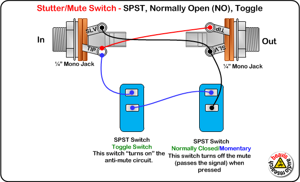
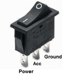
Cut the supply wire in your device. So if a fan is connected to terminal 1 and a motor is connected to.

2 Wire Toggle Switch Diagram H1 Wiring Diagram
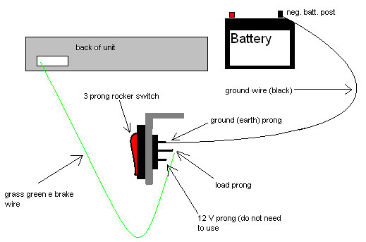
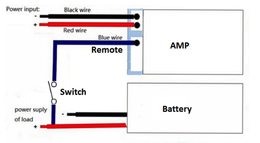
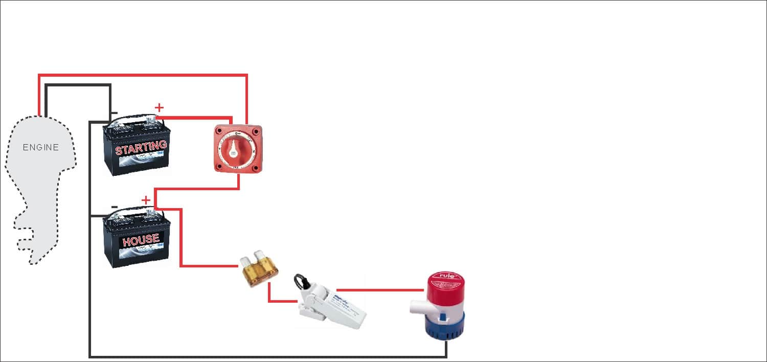
How to wire a stereo to a toggle switch. Personally i find the best way to wire this up is to have both the remote on wire and the main power wire feeding from the commonacc post on the battery switch with the remote on wire running through a dash mounted toggle switch. Applies to spot switches non led switches basic 2 wire switches 2 prong. Either tap inline with the wire coming out of the hu so it will power off with the car. These terminals receive the power necessary to drive the loads on terminals 1 and 5 and 2 and 6. Only requires a 12 hole to mount it and you wont miss the bright red light reminding you to turn it off. Below is the schematic diagram of the wiring for connecting a dpdt toggle switch.
We will now go over the wiring diagram of a dpdt toggle switch. A dpdt toggle switch has 6 terminals. Generally used in 12volt installs for on off switches. This way you can have the stereo working a independent of the ignition switch b running off either battery you select at the battery switch and c turned off completely when the battery switch is in the off position so your battery isnt drained while boat. Use wire cutters to cut your devices supply wire in a location that best allows for routing either or both ends of the wire to the switch. Dpdt toggle switch wiring.
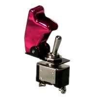
Terminals 3 can flip between terminals 1 and 5. At least i dont. For your toggle switch to function as an on off switch youll need to wire your toggle switch to the devices power supply. Terminals 3 and 4 represent the toggle switch. Or use a bright red led toggle switch tapped into a 12v source. How to wire a toggle switch on off switch basic.

