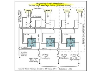
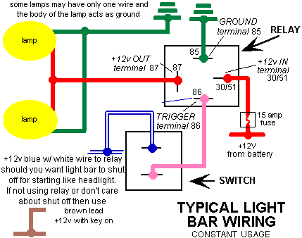
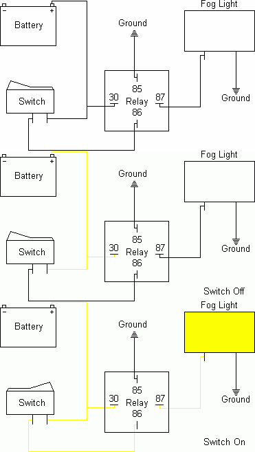
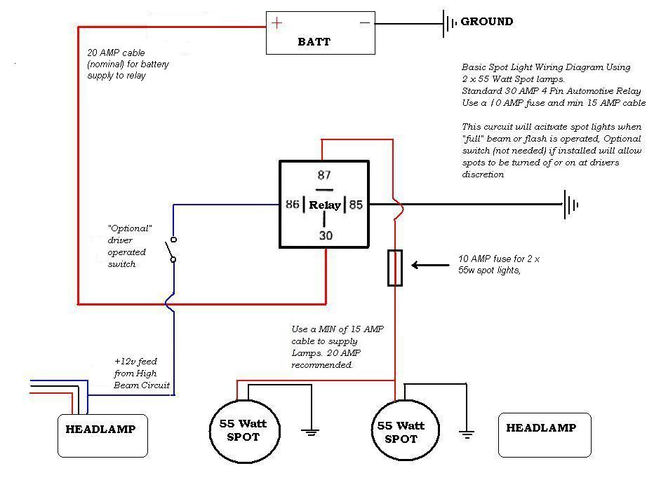
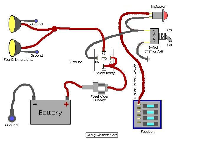
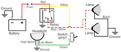
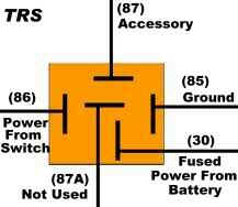
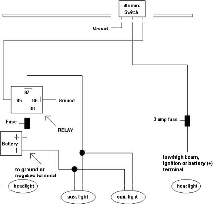
Follow the relays wiring schematic when connecting the wires to the relay one of the relays terminals goes to ground. Off road lights wiring diagram harbor freight off road lights wiring diagram off road light bar wiring diagram off road light switch wiring diagram every electric arrangement is made up of various different parts.
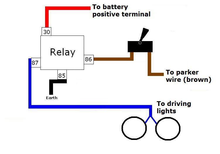
Driving Lights Relay Switch Wiring Diagram H1 Wiring Diagram
Off road light relay wiring diagram. Wiring your off road lights in this fashion helps prevent you from accidentally leaving your headlights on after parking your vehicle. The method i use for wiring the lights and other external accessories for the most part follows the diagram pictured above. If not the arrangement wont work as it should be. For example you could splice a wire off your high beam wire or off your backup light wire 86 connect to a ground. Then run a heavy gauge wire from the battery to the relay placing a 30 amp fuse in line very close. Fog light relay wiring diagram positive ground wiring library fog light wiring diagram with relay.
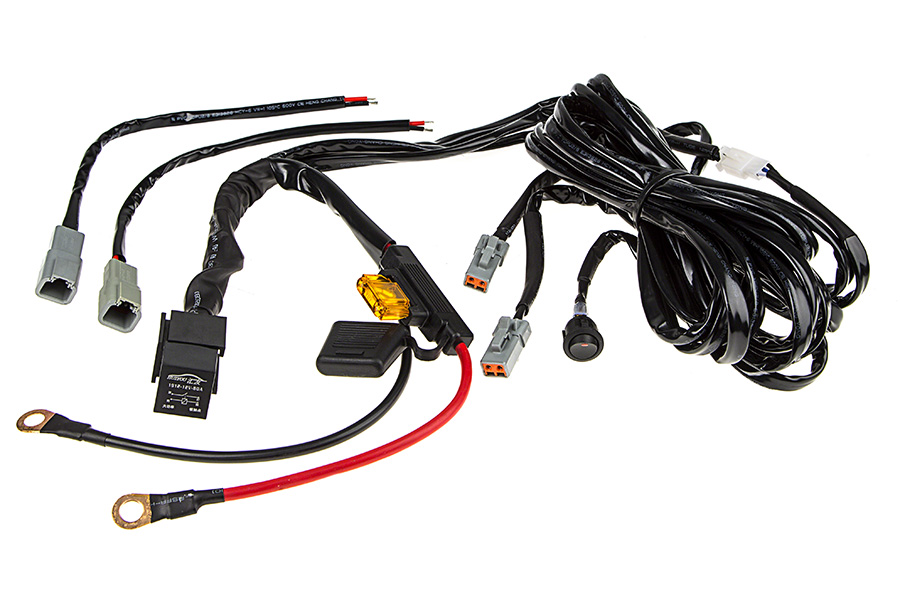
With our wiring harness all you need to do is cut the wire coming from the switch to the 30 prong on the relay and wire it to your high beam lead or your backup light wire. If not with. Nilight led light bar wiring harness kit 12v on off switch power relay blade fuse for off road. That way when you do have your high beams on the current from that goes to the dash switch first and if that is off the electricity cant get to the 8586 circuit to create the magnetic force to close the 3087 circuit which turns on your led lights. Light relay wiring diagram wiring diagram is a simplified good enough pictorial representation of an electrical circuitit shows the components of the circuit as simplified shapes and the skill and signal associates amid the devices. 2 new from 942.
Off road light installation installing off road lights can be a simple straightforward task as long as you closely follow the instructions. With this manual you will be capable to see how each and every element ought to be linked and also the exact actions you ought to take in order to successfully complete a. Without this current no magnetic force is created so the 30 to 87 switch stays open and your lights stay off. Even though the process may seem as easy as 1 2 3 its important to pay attention to the specific gauge or amperage numbers determined for your specific vehicle and electrical load. Another variation to figure 2 is to power the 12v switch lead from your vehicles headlight switch. In this case when you turn off your regular.
It is meant to aid all the typical consumer in creating a correct system. The drawback to this kind of setup is that if you want your lights such as when helping a friend with a trail side repair at night you will need to turn on your ignition in order to turn on your off road lights. A wiring diagram usually gives instruction roughly the relative outlook and settlement of devices and terminals on the devices to incite in building or servicing the device. These instructions will probably be easy to grasp and use. Wiring diagram comes with a number of easy to stick to wiring diagram instructions. Each component ought to be set and linked to other parts in particular way.
As in the diagram a wire is run from a 12 volt power source to the switch in the cab and out to the relay placing a fuse at the source of the power. 85 connects to the power source that you want controlling the switch. 85 and 86 can be reversed.
