Literate in schematic reading. See our engineering essentials page for a full list of cornerstone topics surrounding electrical engineering.

The Schematic Diagram A Basic Element Of Circuit Design
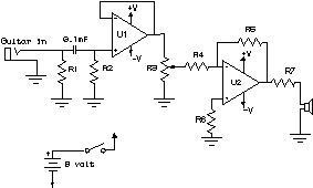
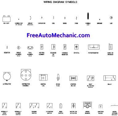
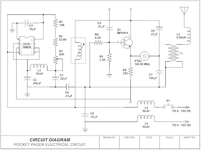
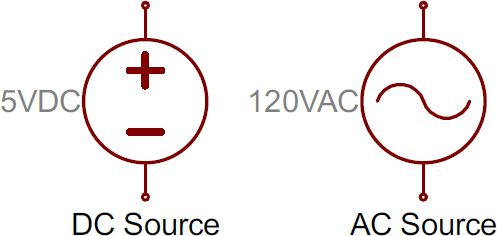
Reading electrical schematics for dummies pdf. A drawing of an electrical or electronic circuit is known as a circuit diagram but can also be called a schematic diagram or just schematic. In addition to the symbols every component on electrical schematics has a unique name and value which further helps to identify what it represents. Component names are usually a combination of one or two letters and sometimes a number. The message in the name. Although initially most circuits may appear complicated recognizing standard symbols and systematic flow tracings simplifies the process. Electrical and electronic schematic symbols in order to understand the functioning of an electrical or electronic circuit you must be able to read the schematic diagram of that circuit.
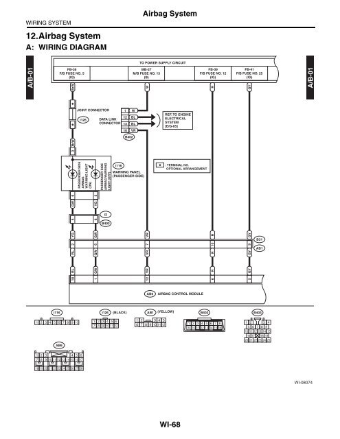
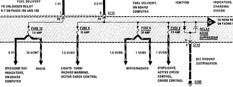
The more you know about the proper procedures for reading and inter preting electrical schematics. A 2 how to read the wiring diagrams composition and contents of wiring diagrams composition and contents of wiring diagrams 1 this manual consists of wiring harness diagrams installation locations of individual parts circuits diagrams and index. Name designators and values one of the biggest keys to being schematic literate is being able to recognize which components are which. Learn to read electrical and electronic circuit diagrams or schematics. Section basic contents wiring harness configuration diagrams connector. Check out some of these tutorial to practice your new found schematic knowledge.
Solidworks electrical comes pre packaged with device libraries containing thousands of symbols 2d footprints and manufacturer parts. Thats all there is to schematic reading. There always exists the method of brute force drafting and then there are intelligent tools to bring your designs to fruition quicker. In general symbols should share a fair amount in common with the real life components they model. Voltage dividers this is one of the most basic. Knowing component symbols following nets and identifying common labels.
Compatible with a variety of file formats such as ms office visio pdf etc. Free download free download free download. 1 drawings representing electronic equipment electrical and electronic technicians are often called on to install and maintain. Accordingly some specifications may not be applicable for individual vehicles. It is also. Feel free to export print and share your diagrams.
In solidworks electrical complex schematics can be created in a matter of minutes and portions of the circuit copied and saved for re use. The component symbols tell half the story but each symbol should be paired with both a name and. In addition to the symbol each component on a schematic should have a unique name and value which further helps to identify it. By tracing the flow in the circuit on should be able to determine how the circuit is designed to operate. Recognizing names and values of schematic symbols name. Understanding how a schematic works opens up the whole world of electronics to you.
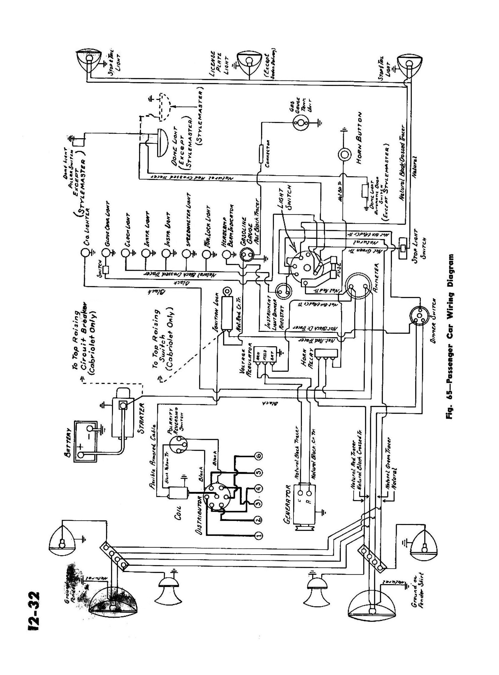
Correct schematic reading is the most important element of hydraulic troubleshooting. Circuit or schematic diagrams consist of symbols representing physical components and lines representing wires or electrical conductors. Just as the road map uses symbols to represent the highways cities. They are normally closed valves that open at a predetermined setting. Wiring diagrams 11 electronic components in schematics 15 mechanical devices 16 passive devices 19 active devices 29 interpreting digital circuit schematics 56 basic digital gates 57 common digital integrated circuits 63 common digital circuit applications 65 common 555 timer circuits 70 reading datasheets 72 self check answers 79 examination 81 v contents contents. A schematic diagram is the road map of the circuit.
2 in each section all specifications are listed including optional specifications. In order to learn how to read a circuit diagram it is necessary to learn what the schematic symbol of a component looks like. Standing of how to read wiring diagrams you fre quently can find the source of the trouble simply by checking the wiring of the unit itself against the man ufacturers wiring diagramthe purpose of this chap ter is to familiarize service technicians with symbols and conventions commonly used in schematic dia grams thereby making it easier to identify compo nents and their related circuits. Reading a schematic this circuit uses two sequence valves. Resources and going further. Once you know how to read an electrical schematic the next step is to design your own.
This process is called reading a. In order to get from one point to another you must be able to follow the appropriate route and understand the meanings of the various symbols found along the way.

