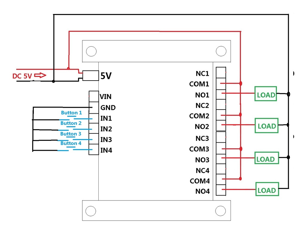
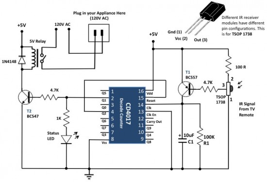
We have used ic 4017 to convert it into a push on push off switch. A 4 channel relay module is used in this project in order to control the light.

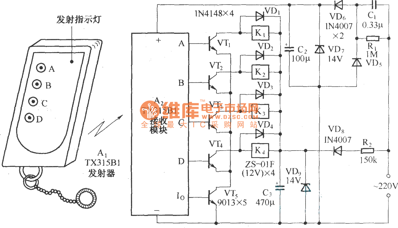
Home Automation With Wireless Rf Remote Control Using 2 Way
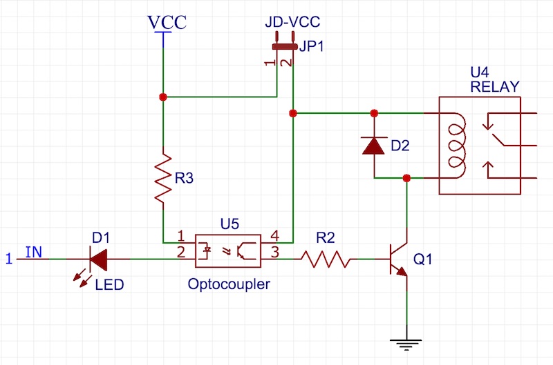
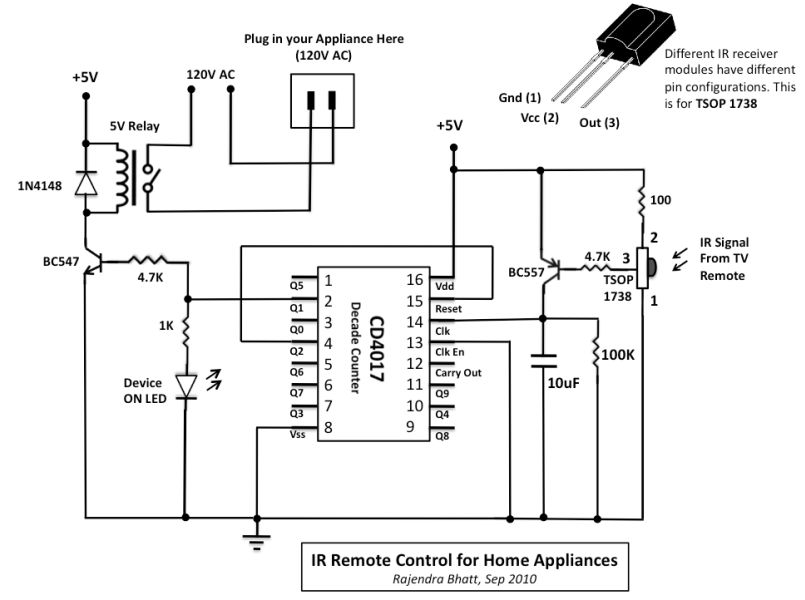
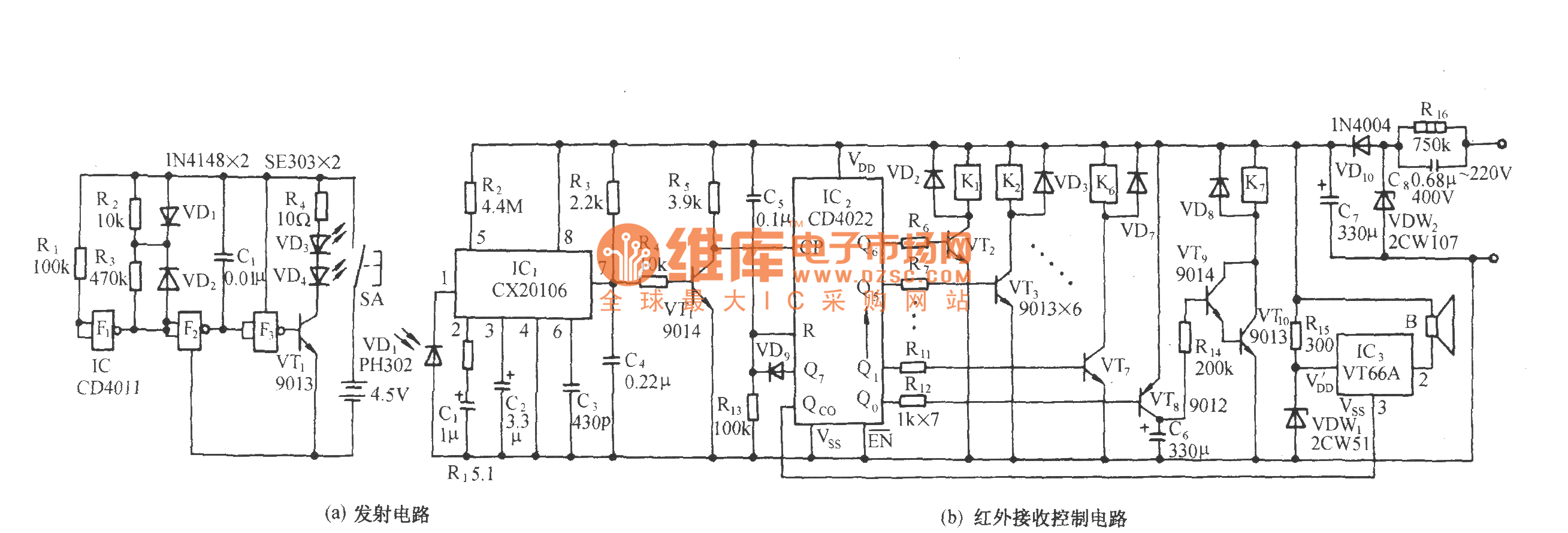
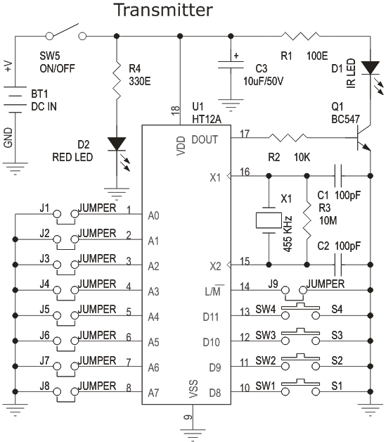
Remote control relay switch circuit diagram. In this remote controlled switch circuit we are using tv remote to onoff the ac light by pressing any button of remote and using the tsop1738 at receiver end. Remote controlled switch circuit diagram notes. Circuit design of remote controlled light switch. The main components of this ir remote control switch are ca 3130 operational amplifier and 4018 counter. Transmitter section and receiver section. This is a project of an rf remote control relay switch circuit.
The post details 3 simple sound activated relay switch circuits which can used as a module for any system that might be assigned to trigger by detecting some kind of sound pressure levelor simply applications such as a voice activated alarm security circuit. Before wiring the circuit make sure that the carrier frequency of the tv remote you have is 38 khzfor that wire the sensor part only point your remote to the tsop1738 and press any switchif out put of tsop1738 goes low then ok your remote is of 38khz typenothing to worry almost all tv. Alternatively the relay circuit can be built as per the circuit diagram. We deliver up to date correct authentic data based on evaluation unbiased at no cost to you. The circuit is using a 5v relay switch at the output from which you can connect any ac appliance like fan light lamp etc. A single channel relay board is sufficient.
If your remote control is not compatible with rc5 codes you can buy a cheap universal remote control to do the job. To do this we display ads from only trusted partners. Kty10 lm2903 temperature sensor relay control schematic circuit diagram. Mains remote switch schematic circuit diagram. The circuit is using a dpdt relay at the output from which you can connect your home appliances to operate them wirelessly like fan lamp etc. We uses normal switch in our daily life and after a long time used to these swithing system we can no more interested in that.
Receiver circuit is connected to ac appliance via relay so that we can control the light remotely. The main components of the project are ic cd4017 and tsop 1738 ir receiver. To avoid the relays changing state owing to a power cut in your home the state of the relays is saved in the microcontroller eeprom and retrieved every time the pic re initialises. The infrared remote control switch is divided into two sections. Ir remote controls switch circuit. In the discussed sound triggered remote control circuit a mic is.
The ca 3130 op amp is a bicmos operational amplifier and it has a high input impedance a low input current and a high speed performance. If you want to operate your home electrical appliances remotely then this ir or infrared remote control switch circuit can be ideal for you. This is the very simple circuit diagram of ir remote control switch. This is a good solution for a unique and so interesting idea to wireless switching system to control the home appliance.
Gallery of Remote Control Relay Switch Circuit Diagram