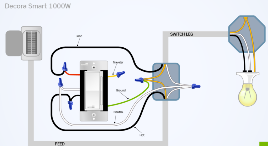
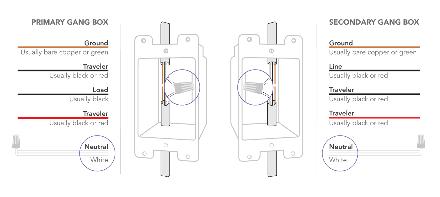
Most smart light switches require a ground wire an in wire an out wire and a neutral wire. Green wire on switch ground line to ground line white wire.

Tp Link Light Switch Wire Instructions Installation
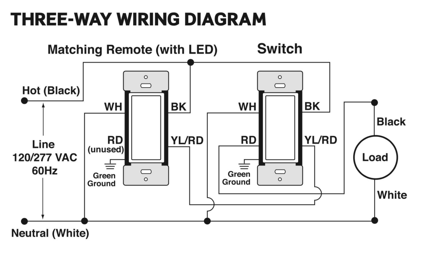
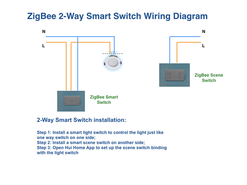
Smart switch wiring diagram. Notice that regardless of whether the switch is on or off there is a clear path from line to neutral that includes r1. The black wire from the other 3 way gets connected to the line black wire. You would be adding neutral either to the line wire coming from your breaker or your load wire going to the switch. The black hot connection is broken to turn the light onoff the white neutral connection completes the circuit. In the above 3 way switch wiring diagram at each switch the black wire gets connected to the copper or black screw. Below is a diagram of a smart switch installed in the first configuration with neutral.
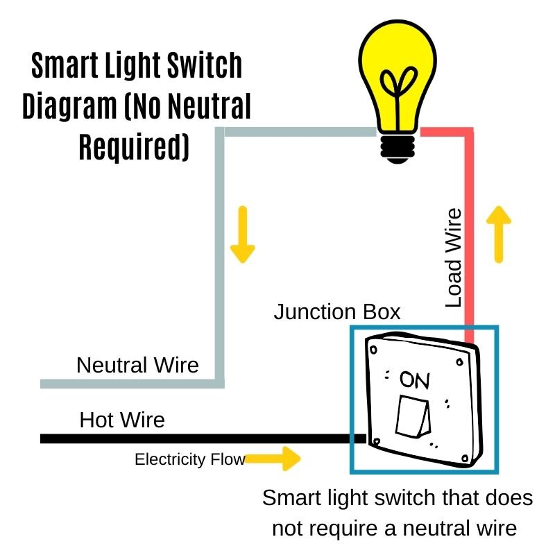
The switch still breaks the circuit but in this case the smart switch can tap into the neutral wire to keep power flowing through the switch the electronics in the switch still break the circuit to the light but the switch maintains a circuit so it is always receiving power. It just doesnt add up. Here is a diagram of a standard switch with a neutral wire. Smart switch with neutral. Connect each of the two black wires from the switch to the available live lines via the wire nut and wrap electrical tape around the wire nuts to make sure the copper conductor is fully concealed. 4 smart switches that work with no neutral wire.
Wiring diagram of a wemo wifi switch with red for load black for line white for neutral and a yellow connected to a green ground wire. March 3 2020 by eric blank. In the ceiling light fixture electrical box one black wire from a 3 way switch gets connected to the black load wire on the light fixture. Click on the image to enlarge and then save it to your computer by right clicking on the image. How can wiring the neutral terminal on a smart switch result in the completion of a circuit with live on one side and neutral on the other. Most homes have the in out and ground wires but some homes.
This is a diagram of a switch with a neutral. A wiring diagram generally provides information regarding the relative setting and also plan of tools and also terminals on the devices in order to help in building or servicing the gadget. Look at the wiring setup. Step 4connect the smart switch wiring with the provided wire connectors as follows. But back to the diagram. It shows the components of the circuit as simplified shapes and also the power as well as signal links in between the tools.
The bare hopefully solid copper wire is the ground. The ground wire from the smart switch needs to be connected to that. Variety of generac smart switch wiring diagram. In your switch box you should have one or more grounding conductors spliced together with a wire connector or wire crimp. Wiring diagram for 20kw generac generator fresh generac smart switch generac smart switch wiring diagram beautiful generac generac generator transfer switch wiring diagram image.

