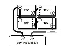
Another option for charging your 24 volt battery bank is to use a 24 volt charger like the samlex sec 2425ul. If your boat has a 24 volt battery system it probably has two 12 volt batteries that are wired together so that the negative post of the first battery connects to the positive post of the second battery.

6 Volt Charging System Wiring Diagram H1 Wiring Diagram
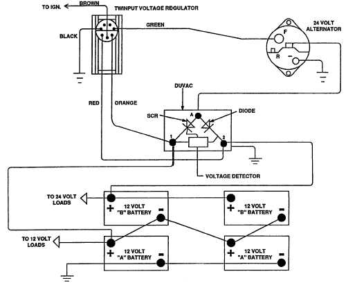
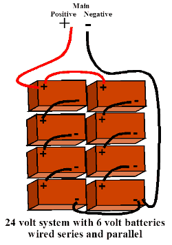
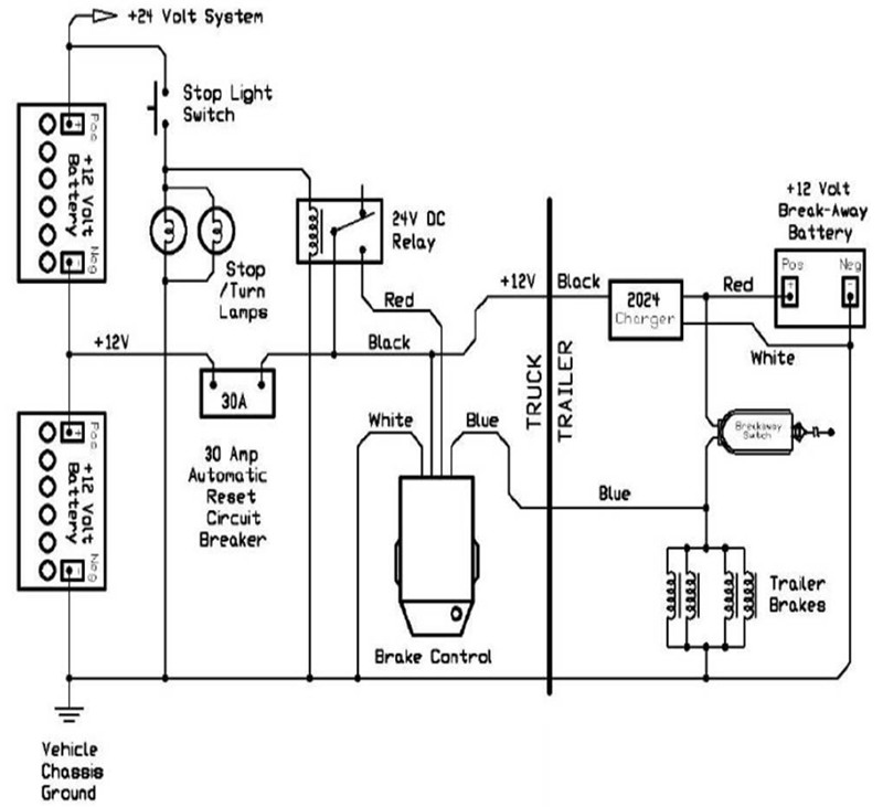
24 volt system diagram. 24 volt systems 2 batteries. The alternators positive and ground. Do not connect 3 twelve volt batteries to run a 24 volt trolling motor. On freshwater fishing boats the most common use for either a 24 or 36 volt battery system is to power a trolling motor. Wire in series only as directed in wiring diagram to provide 24 volts. While small and medium trolling motors use a single 12v marine battery larger trolling motors use larger 24v and 36v systems and require 2 or 3 marine batteries accordingly.
The most popular way to charge a 24 volt trolling motor battery system is with an onboard two bank battery charger like the minn kota mk220d. 24 and 36 volt wiring diagrams. A wiring diagram is a streamlined traditional photographic representation of an electrical circuit. Two 12 volt deep cycle batteries are required. Damage will occur to your trolling motor if you try to connect 36 volts and your motor is only rated for 24 volts. Make sure that the trolling motor is switched to the off position or speed selector set to 0.
It reveals the parts of the circuit as simplified shapes and the power as well as signal links in between the gadgets. Volts and with only 18 volts panel and 12 volts battery bank you would only be able to charge appliances with a lower voltage rating like 12 volt but not 24 volt or higher. But dont get too discouraged this solar arrangement is still useful and practical as long as you dont expect too much out of it. The addition of a high output alternator to your charging system may make it necessary to increase the size. Motorguide 12 24 volt trolling motor wiring diagram just whats wiring diagram. 24 volt alternator installation operation manual introduction.
Trolling motor wiring diagrams. These larger motors and multiple batteries are wired in a series pattern and optimally the circuit. 12 volt system controlling one side of the tractor 3. Harness as indicated in wiring diagram included on page 12. Variety of 12 24 volt trolling motor wiring diagram. 24 volt starting system 2.
If your charger is small enough to be carried aboard your boat you can leave these cables in place since the. A wiring diagram is a kind of schematic which makes use of abstract pictorial signs to reveal all the affiliations of elements in a system. Solar wiring diagram 2. 12 volt system controlling the opposite side of the tractor take one 12 volt system off the tractor and what is left is a typical 12 volt system. With this system the difference is the generator brushes are both connected to the regulator instead of grounding one.


