That being said there is a wide range of different motors and what you have on hand can be completely different. It reveals the parts of the circuit as simplified shapes and the power as well as signal links between the gadgets.
Electrical Winding Wiring Diagrams June 2014
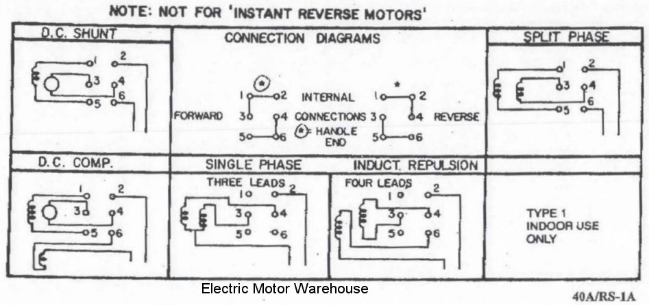
3 phase electric motor wiring diagram. A split phase capacitor start electric motor may be defined as a form of split phase motor having a capacitor connected in series with the auxiliary winding. It is to be. The auxiliary circuit is opened by the centrifugal switch when the motor reaches 70 to 80 percent of synchronous speed. In the united states for low voltage motors below 600v you can expect either 230v or 460v. But before we will disuse. Three phase electricity basics and calculations electrical engineering duration.
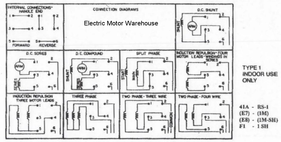
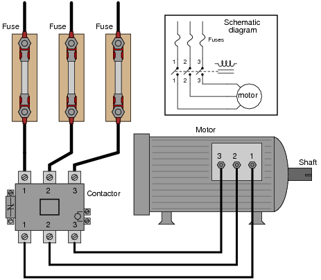
Connecting a 3 phase motor with 1 phase power with diagram duration. Capacitor motor single phase wiring diagrams always use wiring diagram supplied on motor nameplate. A three phase motor must be wired based on the diagram on the faceplate. Motor starter schematic and wiring diagram. It is important to point out from the phasor diagram that the phase difference between im and is is almost 80 degrees as against 30 degrees in a split phase induction motor. Three phase electrical wiring installation in home iec nec.
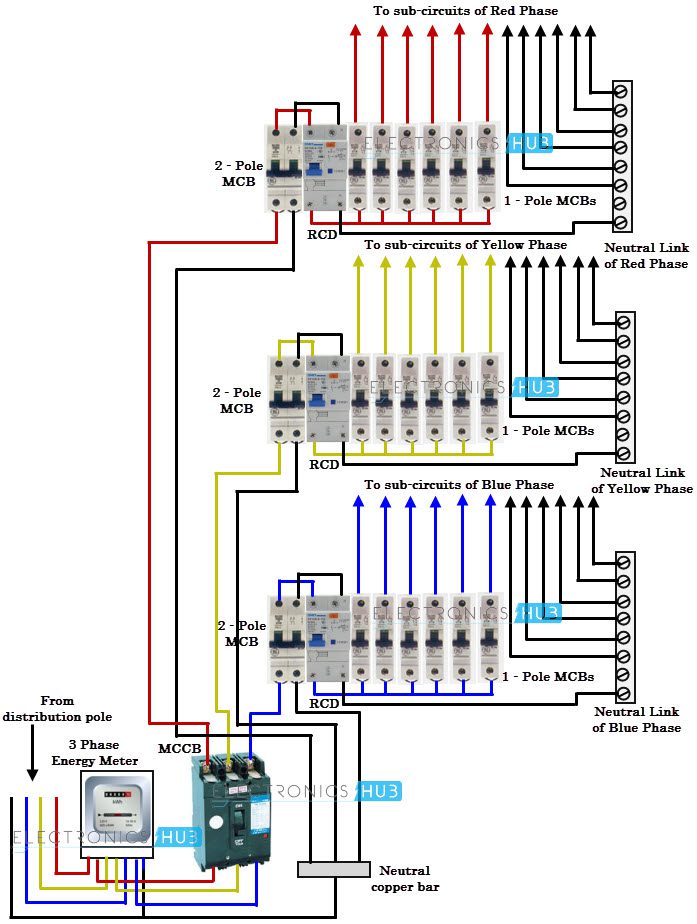
Contactor design and rating contactor nameplate. The first step is to figure out the voltage of your phases. How to wire a contactor and overload. This differs from a schematic layout. Thus a capacitor start induction run motor produces a better rotating magnetic field than the split phase motors. Wiring diagram book a1 15 b1 b2 16 18 b3 a2 b1 b3 15 supply voltage 16 18 l m h 2 levels b2 l1 f u 1 460 v f u 2.
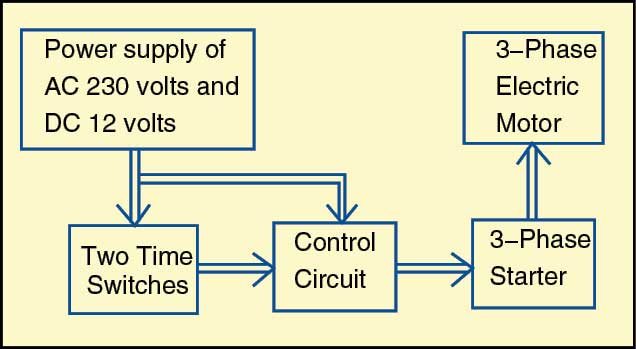
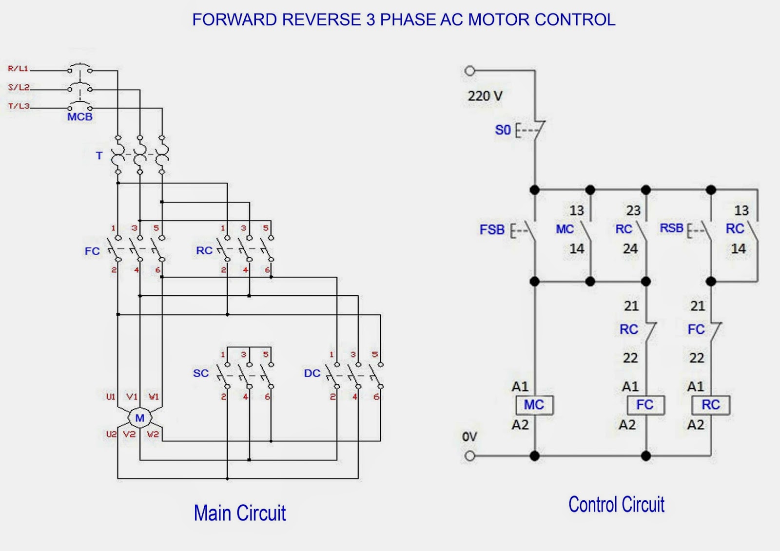
Both 9 wire and 12 wire motors can be connected for high or low voltage operation. A wiring diagram usually gives information about the loved one placement as well as plan of devices and terminals on the devices in order to help in structure or servicing the gadget. A wiring diagram is a streamlined conventional pictorial depiction of an electrical circuit. The figure below shows schematic diagram for industrial three phase wiring. Three phase power from the utilities is connected to the main breaker through three phase energy meter. L1 to t1 l2 to t2 l3 to t3 t4 to t7 t5 to t8 and t6 to t9.
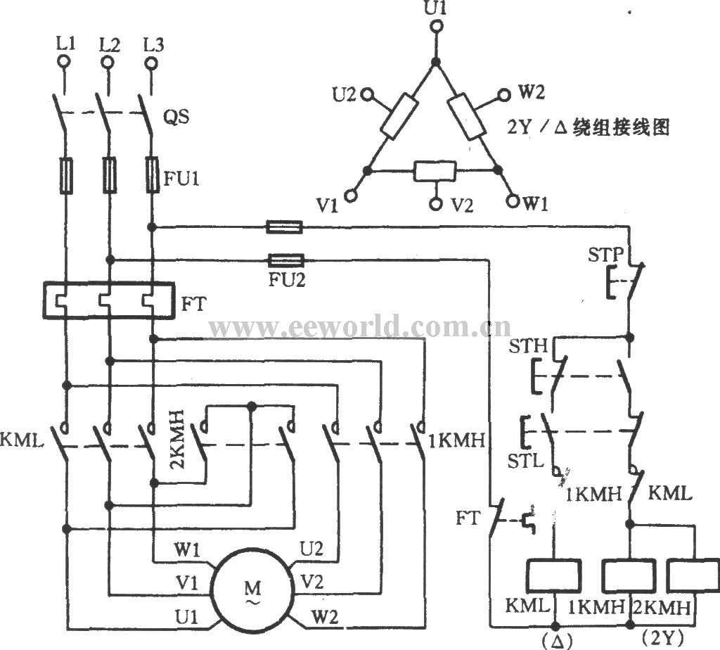
Ac blower motor wiring diagram furthermore 3 phase star delta motor connection diagram besides dc electrical motor wiring diagram further 813 tube lifier schematic furthermore three phase induction motor rotor and stator. The other 9 wires would be connected as in a 9 wire motor note in a 9 wire motor the equivalent of t10 t11 and t12 are internally connected together. Collection of 3 phase electric motor starter wiring diagram. It is evident from the phasor diagram that the current through the starter winding is leads the voltage v by a small angle and the current through the main winding im lags the applied voltage. A 9 wire motor can only be connected in a wye configuration whereas a 12 wire motor can be connected in either a wye or delta configuration. The power in the main breaker is then given to various busbars.
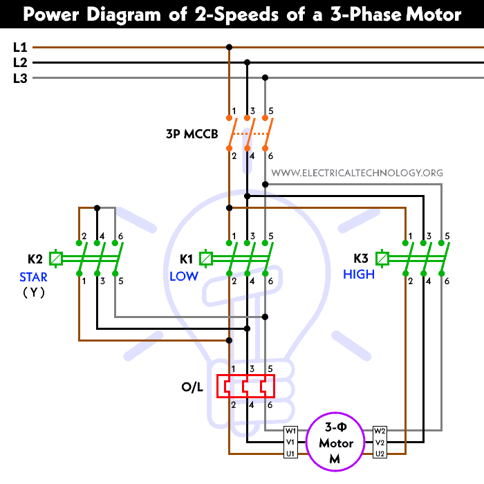
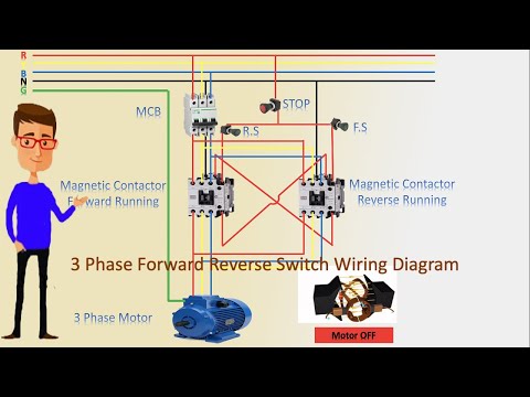
Multi speed 3 phase motor 3 speeds 1 direction power control diagrams one line diagram of simple contactor circuit. The engineering mindset.
Gallery of 3 Phase Electric Motor Wiring Diagram