To make this circuit work a 3 way dimmer can be used in place of one or both of the standard 3 way switches. In response to the requests for this information i have developed a comprehensivestep by step guide designed to walk you through the identification and wiring of your 3 way switches.

Tf 6821 Wiring Diagram For 3 Way Switches Free Download
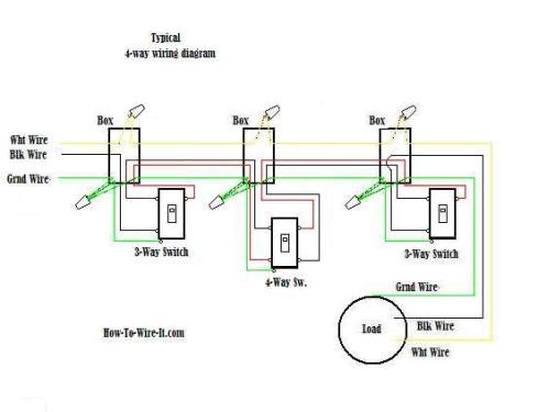
4 way switch wiring diagram pdf. Four way switch wiring instructions inside the switch packaging. 4 way switches have four terminals each with two pairs of travelers one set usually black and one set usually brass color. This is the wiring for a dimmer in a 4 way circuit. In fact a dimmer can be used this way in place of any of the 3. Conventional 4 way switch wiring. The system is often used in staircases to control the lighting at three different levels and in rooms with several entry points.
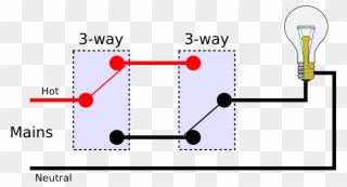
The wiring connections on 4 way switches varies between manufacturers. 3 way switch wiring diagram helpful for wiring 4 way switches which are wired with 3 way switches. The white wire becomes the energized. Attach the black and whiteblue traveler wires entering the 4 way switch box to the in terminals often the top terminals on the 4 way switch black on the left top pole and whiteblue on the right top pole. 2 xx color codes see section colors and finishes on the next page. A four way switch system consists of three or more switches to control the same light.
The set up consists of two 3 way switches and one or more 4 way switches see illustration below. 18005239466 dimmers create ambiance and save energy lutron 191 lutron wiring diagrams wiring diagram 6 3 way wiring control line side 3 way switch dimmer switch fan control dimmer switch fan control lighting load. Not for use in 4 way mechanical switch applications. 3 for clamshell packaging add h after 153m. Notice that the switches do not. 4 way dimmer switch wiring diagram.
Sometimes there is only a switch wiring diagram printed on the inside of the 4 way switch package box. Three wire cable runs between all the switches and 2 wire cable runs to the light. A four switch configuration will have two 3 way switches one on each end and two 4 way switches in the middle. With 4 way switches you must read the manufacturers instructions or wiring diagram. Some 4 way switches may have the in and out pairs opposite each other rather than top and bottom. This 4 way switch diagram 2 shows the power source starting at the fixture.
I have a few of the most common ways in wiring a 4 way switch to help you with your basic home wiring projects. In the diagrams below the first switch 3 way common terminal connects to. 4 way switch wiring diagrams this 4 way switch diagram 1 shows the power source starting at the left 3 way switch. 1 an additional wiring and programming step is required for 3 way mechanical switch applications. The white wire of the cable going to the switch is attached to the black line in the fixture box using a wirenut. Not available in br or gr.
A 4 way switch wiring diagram is the clearest and easiest way to wire that pesky 4 way switch.


