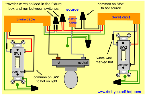
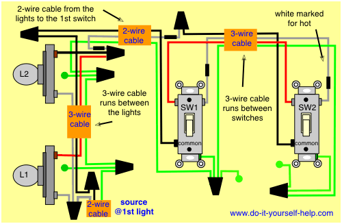
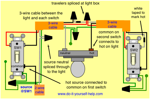
At the ceiling box the ungrounded conductor aka hot from the fan connects to the black wire from the switch 1. A three way switch is used to control a fixture from two different locations.
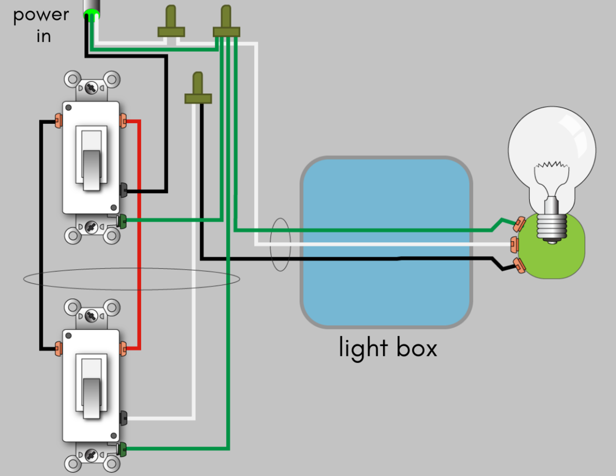
How To Wire A 3 Way Switch Wiring Diagram Dengarden
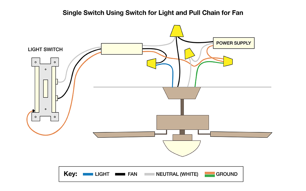
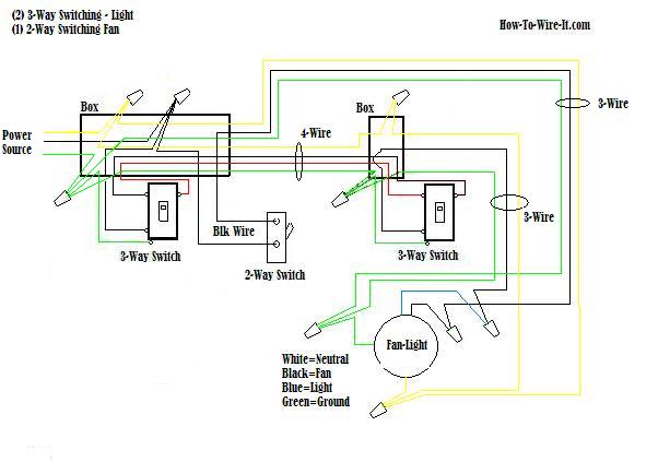
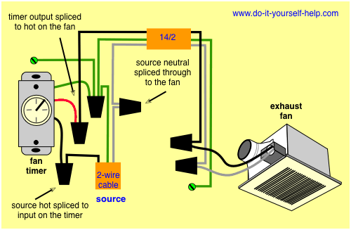
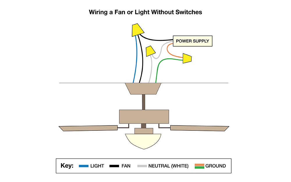
Ceiling fan and light on separate 3 way switches. It shows what sort of electrical wires are interconnected and can also show where fixtures and components may be. I also used a diagram picture thanks for watching. I explain how i wired a ceiling fan on one part of the switch and the light on the 3 way part of the switch. The traveler wires are spliced together in the ceiling fixture box to run between switches. A three way switch can be used to control the fan and light individually from each location or combined with one. A wiring diagram is a streamlined conventional photographic depiction of an electrical circuit.
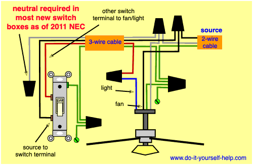
So leave the three way switches as they are and get a qualified electrician to install a new 142 conductor from one of the switchboxes up to the light fixture. The common on the second 3 way switch is connected to the hot wires on the fanlight. You want to be able to split that out so youll need an additional hot feed one for the fan one for the light. Splice both the fan and the light hot wires together with the common wire from the sw2. In roughing in wiring for a ceiling box that has a potential to have a ceiling fan installed either now or in the future it prudent to wire the circuit for separate control of the fan and the light kit on individual switches. Wiring diagram 3 way switch ceiling fan and light what is a wiring diagram.
The travelers do not connect to the fan or light. A wiring diagram is a straightforward visual representation of the physical connections and physical layout of the electrical system or circuit. Assortment of wiring diagram 3 way switch ceiling fan and light. This article describes a fan or light switched separately power source at light and light controlled by two 3 way switches and fan at one location only 3 wire plus ground cable being routed thru the ceiling box between switches. It shows the elements of the circuit as streamlined forms and also the power and also signal connections in between the devices.

