The arm is spring loaded and is rotated in the clockwise direction gradually reducing the armature resistance as the motor accelerates. Diodes d1 and d2 rectify the ac voltage to dc.

Forbix Semicon Wireless Remote Motor Control Water Pumps
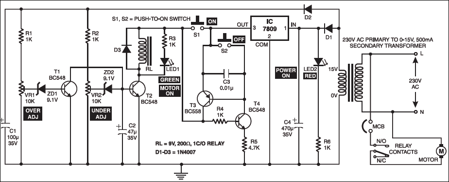
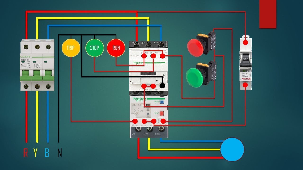
Electronic motor starter circuit diagram. Question 5 although across the line motor control circuits are simple and inexpensive they are not preferred for starting large motors. This motor starter protects singlephase motors against voltage fluctuations and overloading. A starter also self starter cranking motor or starter motor is a device used to rotate crank an internal combustion engine so as to initiate the engines operation under its own power. The main heart of dol starter is relay coil. Its salient function is a soft onoff electronic switch for simple operation. A direct online starter consits of two buttons a green button for starting and a red for stopping purpose of the motor.
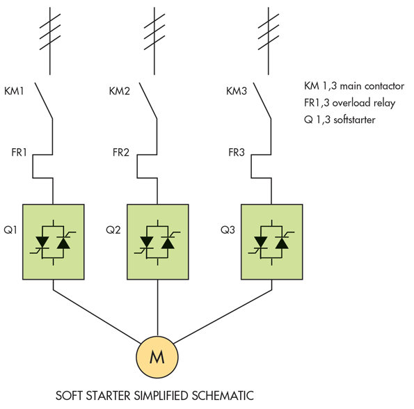
The above diagram is the schematic diagram of an electronic motor starter circuit. Normally it gets one phase constant from incoming supply voltage a1when coil gets second phase relay coil energizes and magnet of contactor produce electromagnetic field and due to this plunger of contactor will move and main contactor of starter will closed and auxiliary will change its position no become nc and nc become shown red line. A wiring diagram usually gives information about the loved one placement as well as plan of devices and terminals on the devices in order to help in structure or servicing the gadget. These solid state switches are phase controlled in a similar manner to a light dimmerthe average voltage is controlled by varying the conduction angle of the switchesincrease the conduction angle will increase the average output voltagethe power dissipation in the starter during start. A wiring diagram is a streamlined conventional pictorial depiction of an electrical circuit. Direct on line starter wiring diagram.
Inside the protection circuit transistor t1 is utilized to. Internal combustion engines are feedback systems which once started rely on the inertia from each cycle to initiate the next cycle. Identify some of the reasons across the line starting is undesirable. The above diagram is the schematic diagram of an electronic motor starter circuit. Its salient function is a soft onoff electronic switch for simple operation. Figure 2 shows a manual starter circuit diagram.
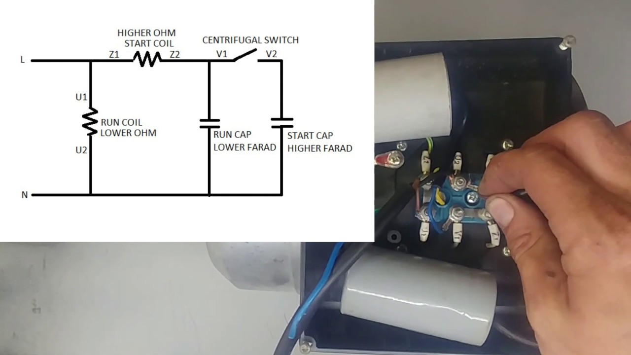
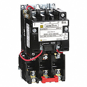
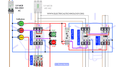
This motor starter protects singlephase motors against voltage fluctuations and overloading. The unregulated power supply is given towards the protection circuit. The electromagnet that holds the starter in the run position is in the field circuit. Collection of 3 phase electric motor starter wiring diagram. This starter is a so called three point starter. In the above one phase motor wiring i first connect a 2 pole circuit breaker and after that i connect the supply to motor starter and then i do cont actor coil wiring with normally close push button switch and normally open push button switch and in last i do connection between capacitor start motor and contactor.
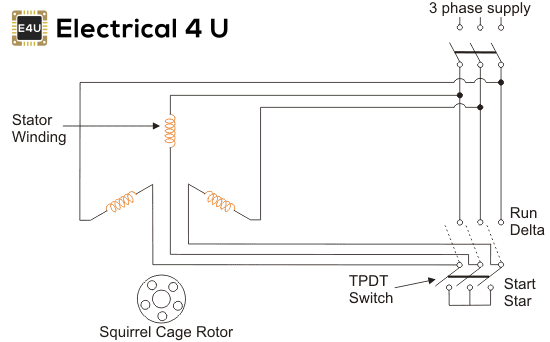
Wiring diagram of dol starter. Starters can be electric pneumatic or hydraulicin the case of very large engines the starter can even be another internal combustion engine. An alternative to across the line motor starting is reduced voltage starting. This differs from a schematic layout. If there are no convenient motor control circuit diagrams available for illustration you may want to ask a student to draw an across the line starter circuit on the whiteboard for everyone to see. The transformer steps down the ac voltage from 230v to 15v.
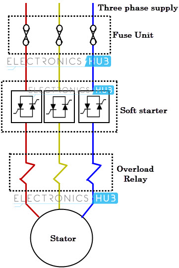
The dol starter comprises of an mccb or circuit breaker contactor and an overload relay for protection. A soft starter is another form of reduced voltage starter of ac induction motorsthe soft starter employes the solid state devices to control the current flow and therefore the voltage applied to the motor. Working principle of dol starter. The above diagram is a complete method of single phase motor wiring with circuit breaker and contactor. The transformer steps down the ac voltage from 230v to 15v. The wiring diagram for a dol stater is shown below.
It reveals the parts of the circuit as simplified shapes and the power as well as signal links between the gadgets.
Gallery of Electronic Motor Starter Circuit Diagram